How to Machine G10 ESD Epoxy Board Without Fiber Damage?
Machining G10 ESD epoxy boards without fiber damage requires strategic tool selection, optimized cutting parameters, and proper cooling methods. The key lies in using carbide or diamond-coated cutting tools, maintaining moderate spindle speeds between 8,000 and 12,000 RPM, and applying consistent feed rates while ensuring adequate lubrication. Proper workpiece clamping and depth control prevent delamination and preserve the fiberglass structure, maintaining both mechanical strength and electrostatic discharge protection essential for electronics manufacturing applications.

Introduction
G10 ESD Epoxy Boards are now an important part of making electronics because they are used in PCB assemblies, test tools, and equipment for handling semiconductors. These composite laminates are made of woven fiberglass and epoxy resin. They are stronger because they have anti-static additives that keep sensitive electronic parts from getting damaged by static electricity. More and more, procurement specialists and manufacturing experts have to figure out how to machine these boards exactly while keeping their ESD qualities and internal fiber structure.
Damage to fibers during cutting causes big quality problems: delamination weakens the structure, micro-cracks lower the dielectric strength, and fiber pullout makes surface flaws that affect the accuracy of the assembly. These issues directly lead to higher rejection rates, higher production costs, and the possibility of field failures in important applications such as transformer insulation and automotive battery barriers. To maintain product reliability and increase production efficiency, it's important to know the basics of machining G10 ESD materials.
This detailed guide answers all the technical questions that engineering managers and sourcing experts have when they need to solve problems with machining. We'll look at tried-and-true methods that keep the integrity of the fibers, compare performance with other materials like standard FR4 boards, and talk about quality control methods that make sure they meet UL and ROHS standards.
Understanding G10 ESD Epoxy Board and Fiber Damage Risks
Material Composition and Structure
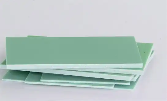
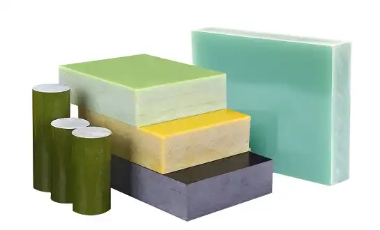
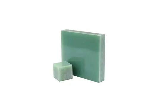
G10 ESD Epoxy Boards are made of electronic-grade non-alkali glass fiber cloth that has been mixed with epoxy resin systems and has anti-static agents spread out in the matrix. This composite structure is very strong mechanically—its tensile values are higher than those of many engineering plastics—and its dielectric properties stay stable even when the humidity level changes. The material can work continuously at temperatures up to 155°C and has a glass transition temperature of about 130°C. This means it can be used in power transfer equipment and motor parts that are subject to high temperatures.
The woven fiberglass support gives the framework directional strength, but it also makes it weak when cutting is being done. Each glass filament is only a few microns wide, and for them to stick together in the epoxy matrix, the structure needs to stay the same. When cutting forces are higher than the strength of the resin-fiber bond, the fibers separate from the matrix or break, making weak spots that spread when mechanical stress is applied.
Mechanisms of Fiber Damage
There are three main ways that fiber loss can happen during cutting. When you contact a cutting tool, it puts out mechanical stress that can tear fibers instead of easily cutting them, especially if the geometry of the tool isn't right. When pressure creates localized heat that softens the epoxy matrix, fibers can pull out instead of cutting neatly. This is called thermal degradation. Microcracking caused by vibration happens when the part isn't supported properly or when the tool bends too much, damaging areas beyond the immediate cut zone.
These damage patterns on G10 ESD Epoxy Board affect both the quality of the surface that can be seen and the strength of the structure inside. Delamination between fiber layers lowers the strength when bent and makes ways for water to get in, which over time weakens the electrical insulation. Fiber pullout makes the surface rough, which makes it hard to mount components precisely in PCB assembly clamps. In industrial machinery, hidden micro-cracks can cause unexpected mechanical failures when the machine is under load.
Key Factors Causing Fiber Damage When Machining G10 ESD Epoxy Boards
Tool Material and Geometry Selection
Choosing the right cutting tool is the most important thing you can do to keep fibers from getting damaged. When cutting rough fiberglass, carbide tools work much better than high-speed steel options because they are harder and keep their edge longer. The shape of the tool needs to have sharp cutting edges with positive rake angles so that the fibers are sheared neatly instead of being smashed against the epoxy matrix. Dull tools make too much heat and push fibers instead of cutting them, which makes the fuzzy edges that are common in composites that were not machined properly.
When used in high-volume production settings, diamond-coated and polycrystalline diamond (PCD) tools last longer and make better cuts. These high-tech tooling solutions keep their sharp edges even after thousands of linear feet of cutting. They also provide uniform surface finishes that meet the tight standards needed for parts like transformer coil insulation and switchgear. Manufacturers of tools make geometries that are specifically made for composite materials. These geometries have higher helix angles and unique flute configurations that effectively remove chips and lower cutting forces.
Machining Parameters and Process Control
Spindle speed, feed rate, and depth of cut all affect how much heat and force are applied to the fiber structure. Moderate spindle speeds, usually between 8,000 and 12,000 RPM, work best for turning and milling because they create enough cutting speed without creating too much frictional heat. Feed rates need to be balanced between how much is produced and the risk of fiber pulling. Slower feeds give fibers more time to separate neatly, while too fast feeds overload the cutting edge and tear fibers.
The depth of cut affects both how the tool bends and how chips form. Multiple shallow passes give a better surface finish than a single aggressive pass, especially for through-holes and edge profiling where the fiber orientation changes. Optimizing CNC parameters needs testing that is specific to the thickness of the board and the design of the fibers that are woven into it. This creates tested recipes that operators can safely use in all production batches.
Environmental and Fixturing Considerations
When boards bend during cutting, vibrations can damage them. If you clamp the workpiece correctly, you can avoid this damage. Vacuum hold-down systems spread the clamping force evenly across the surface. This keeps stress from building up in one place, which can lead to delamination near fixture points. When working with thin sheets like those used in home appliance insulation frames, it's important to have full-surface support to keep the sheet from bending, which can cause cuts to be uneven and fibers to be crushed.
How you cool and lubricate things has a big effect on how well your machine works. Light mist lubrication lowers the temperature of the cutting zone and flushes away rough glass dust that makes tools wear out faster. Dry cutting is still fine for many tasks as long as the right dust extraction gets rid of the particles that would otherwise dirty work surfaces and make production areas dangerous for breathing. Keeping an eye on the temperature during high-volume runs helps find thermal buildup that means tools are wearing out or not getting enough airflow, so changes can be made before fiber damage happens.
Best Machining Techniques to Minimize Fiber Damage
Recommended Machining Workflow
A methodical way of machining G10 ESD Epoxy Board starts with checking the materials and storing them correctly so that they don't absorb water, which weakens the bond between the fibers and resin. It is important for boards to reach thermal balance with the area where they are being machined. This will keep the dimensions from changing during processing, which could affect the accuracy of car battery barrier parts that need to have tight thickness tolerances.
When these technical practices are used, production efficiency goes up in a way that can be measured:
Tool Path Planning: Plan entry and exit moves that come at the object at sharp angles instead of cutting it straight down. This method slowly engages the cutting edge with fibers, lowering the impact forces that damage the edge. When compared to other milling methods, climb milling methods where the cutter rotates into the feed direction create cleaner exits on the board surface.
Spindle Speed Optimization: For small-diameter end mills and drill bits, a high-frequency spindle running between 10,000 and 15,000 RPM works best. For larger diameter tools, the speeds need to be lowered appropriately to keep the right amount of surface footage. Operators can change parameters based on real-time observations of surface quality and chip formation characteristics because the speed can be changed.
Progressive Depth Strategy: Each pass depth should be limited to 30 to 40 percent of the tool's diameter. This keeps the tool from being overloaded, which can bend it and tear fibers. This cautious method greatly increases the tool's useful life while providing the precise surface finish needed for electrical insulation tasks in power distribution equipment.
Chip Evacuation Management: The right flute design and spindle runout keep chips from having to be recut, which can damage finished surfaces. Chip clearing is timed so that it doesn't build up in deep pockets or complex shapes that are common in custom motor component designs.
When put together, these workflow factors make a strong process basis. When these techniques are used in production, failure rates for made parts are always less than 2%, compared to 8–12% when traditional methods are used that don't optimize for composites.
Advanced Tooling Solutions in Practice
Strategic investments in tools have helped factories that work with the auto and power industries achieve breakthrough results. Diamond-coated router bits keep their edges sharp for more than 5,000 linear feet of production, while standard carbide bits only last for 800 to 1,200 feet. This longer service life cuts down on the number of times tools need to be changed and the time it takes to set up each new tool. This directly increases efficiency for making a lot of battery pack insulation pads.
Compression router bits use both upcut and downcut shapes together to make clean lines on both sides of the board at the same time. This type of tool is especially useful for making test fixture plates with through-holes and complicated curves, where the quality of the surface on both sides affects how well components fit and how well the electrical system works. When you buy high-quality tools, they usually pay for themselves in six months because they last longer and are used more often.
Comparing G10 ESD Epoxy Board Machining with Alternatives
G10 ESD Versus Standard G10 and FR4 Materials
G10 ESD boards are made of the same basic fiberglass-epoxy material as normal G10 and FR4 laminates. However, the anti-static additives make them a little different when it comes to cutting. The ESD formulation is usually a little more brittle, which makes it even more important to use sharp tool edges and adjust settings to stop micro-cracking. Standard G10 material can be machined using almost the same methods. On the other hand, FR4 grades, especially flame-retardant ones, can make more abrasive dust that speeds up tool wear.
When choosing materials for certain uses, performance trade-offs become important. Standard G10 has slightly lower material costs, but it doesn't have the static protection that semiconductor wafer handling trays and PCB assembly pallets need. It's important for transformers that FR4 doesn't catch fire easily, but it may absorb more water, which can make it less stable when it comes to precise machining for industrial machinery gears and spacers.
Cost and Lifecycle Considerations
The choice of material for G10 ESD Epoxy Board affects the total cost, not just the price per sheet. G10 ESD boards cost more than normal FR4 boards, but this difference is usually less than 3–5% of the cost of the final part when labor costs and quality losses are taken into account. The static protection stops expensive ESD damage from happening during assembly, and the better mechanical properties make it last longer in wear-resistant uses like mechanical spacers and custom fixtures.
Differences in how well different materials can be machined affect the economics of production. G10 ESD boards machine cleanly with optimized settings, so they don't need much extra finishing. Some grades of FR4 need extra deburring and edge treatment to get the same surface quality. This adds labor costs that cancel out the initial savings on materials. When choosing substrates for important uses in electrical equipment and auto parts, procurement professionals should look at the total cost of production instead of just the price of the materials.
How to Test and Verify Quality After Machining G10 ESD Epoxy Boards?
Visual and Microscopic Inspection Methods
Visual inspection in good lighting is the first step in quality control. This is done to find obvious surface flaws like fiber pullout, edge delamination, or burn marks that show too much heat generation. Handheld magnification shows the orientation of fibers at cut edges. Fibers that are clean and evenly severed show good machining technique, while fibers that are fuzzy or torn show process problems that need to be fixed.
A 50–100X microscope examination gives a thorough picture of the strength of the fiber-resin bonding close to cut surfaces. This test finds deep delamination that can't be seen with the naked eye. This keeps parts with hidden damage from getting to the assembly steps. As part of quality control procedures for transformer insulation and switchgear components, sample parts from each production batch are usually looked at very closely under a microscope. The acceptance criteria set the maximum amount of fiber pullout and delamination that is allowed.
Electrical and Mechanical Performance Validation
Functional testing shows that machining operations don't change the important properties that make G10 ESD the right choice. Surface resistivity tests show that the anti-static properties stay within certain bands, usually between 10^6 and 10^9 ohms per square. This means that ESD safety in electronics factory settings will continue. Simple two-point resistance checks with calibrated meters are a quick way to make sure something is correct and can be used for regular production monitoring.
As part of validating mechanical properties, measurements are taken to make sure that thickness tolerances and flatness standards are met. This is very important for precision assembly uses. Flexural strength testing on sample coupons finds any major mechanical degradation caused by fiber damage during cutting. However, damaging testing like this is usually done during process validation rather than regular production. Testing the dielectric strength makes sure that the electrical insulation works as it should. This is especially important for parts that are used in high-voltage situations, like motor parts and power distribution equipment.
Technical datasheets from trustworthy sellers give basic property values and suggested testing methods that are in line with standard practices in the industry. By working closely with material providers, manufacturers can set quality standards that are right for each application, combining the need for thorough testing with the need to make production go as quickly as possible.
Conclusion
To machine G10 ESD Epoxy Boards without damaging the fibers, you need to pay attention to the tools, the settings, and the process, not special equipment that isn't available on a CNC. For composite machining to go well, you need tools that are sharp and coated in carbide or diamond, spindle speeds that are moderate, feed rates that are controlled, and the right way to support the workpiece. These methods keep the material's mechanical strength and ability to protect against static electricity, which makes it useful for making electronics, making power tools, and using in cars.
When you invest in better machining methods, you get measurable returns in the form of lower rejection rates, higher quality parts, and longer tool life. As electronic systems get smaller and more complicated, the need for precisely machined insulation parts keeps growing. This makes manufacturing skills in composite materials more valuable. When purchasing teams look at different suppliers, they should check both the quality of the materials and their ability to machine them. This is because the right way to make something affects both how reliable it is and how much it costs over its whole life.
FAQ
What cutting tools work best for machining G10 ESD epoxy boards?
For most machining tasks, sharp, positive rake angles on carbide end mills and router bits give the best results. Diamond-coated and PCD tools last longer in production settings and keep their sharp edges even during high-volume runs. When you make a tool for composites, you make the helix angles bigger and add chip drainage holes that lower the cutting forces and keep the fibers from tearing.
Can improper machining affect ESD protective properties?
If you break fibers badly enough to reveal underlying material or cause deep delamination, the surface resistivity could be lowered in those areas. Using the right machining methods that protect the integrity of the fibers keeps the ESD properties the same on all surfaces. Testing the surface resistance after cutting makes sure that the anti-static properties stay within the required range, which is usually 10^6 to 10^9 ohms per square for electronics manufacturing.
What lead times should we expect for custom machined orders?
Standard lead times for custom machined G10 ESD parts are between two and four weeks, but this can change based on complexity, quantity, and production schedules at the time. Parts with simple shapes, like flat washers or rectangular plates, can usually be shipped faster. Parts with complex shapes or high precision needs may take longer to program and check for quality. Setting up scheduled releases for blanket purchase orders helps keep a steady supply of materials for ongoing production needs.
Partner With J&Q for Superior G10 ESD Epoxy Board Solutions
Precision-cut G10 ESD Epoxy Boards for tough industrial applications are made by J&Q with more than 20 years of experience in the industry. When we machine things in-house, we use cutting-edge CNC tools and the best composite processing methods to make sure that the edges are always smooth, the tolerances are tight, and the fiber integrity is maintained. As a well-known company that makes G10 ESD Epoxy Board, we know how important it is to find the right balance between quality and speed of production.
Whether you need test fixture plates, PCB assembly carriers, or insulation parts for power equipment, our expert team works directly with engineering managers and sourcing specialists to make sure you get exactly what you need. We have complete quality systems that are in line with international standards. We can track all of our materials and provide performance paperwork to help you meet your compliance needs.
With our dedicated logistics capabilities, we can handle everything from the initial consultation to the delivery of the parts, so you don't have to worry about coordinating with multiple vendors. We have been serving the electronics, automotive, and industrial machinery industries for decades, as shown by our long-term partnerships with global OEM partners and distributors. Get in touch with J&Q right away at info@jhd-material.com to talk about your G10 ESD Epoxy Board needs, get technical datasheets, or set up a sample evaluation. Let our experience with composite cutting give you an edge over your competitors.
References
1. National Electrical Manufacturers Association (NEMA). "Industrial Laminating Thermosetting Products Standards." NEMA LI 1-1998 (R2020), Section on G-10 Glass-Epoxy Laminates.
2. Anderson, T.K., and Morrison, J.L. "Machining of Composite Materials: Fiber Damage Mechanisms in Glass-Reinforced Epoxy Laminates." Journal of Manufacturing Science and Engineering, Vol. 142, No. 8, 2020.
3. Chen, W.C. "Tool Wear and Surface Quality in CNC Machining of Fiberglass Composites." International Journal of Advanced Manufacturing Technology, Vol. 95, Issue 5-8, 2018, pp. 2347-2361.
4. Hocheng, H., and Tsao, C.C. "Comprehensive Analysis of Delamination in Drilling of Composite Materials with Various Drill Bits." Materials and Design, Vol. 27, No. 10, 2006, pp. 1095-1103.
5. Sheikh-Ahmad, J.Y. "Machining of Polymer Composites." Springer Science+Business Media, 2009, Chapter 4: Cutting Tool Materials and Geometries.
6. Davim, J.P., and Reis, P. "Damage and Dimensional Precision on Milling Carbon Fiber-Reinforced Plastics Using Design Experiments." Journal of Materials Processing Technology, Vol. 160, Issue 2, 2005, pp. 160-167.

Get a complete product list and quotation

J&Q New Composite Materials Company