Precision Tolerance Control in CNC Machined FR4 Components
To keep precise tolerances on CNC-machined FR4 component, you have to pay close attention to the features of the material, the cutting settings, and the quality control systems. Because FR4 is a flame-resistant glass-epoxy combination, each part needs to be made using specific methods to get the dimensions right (within ±0.001 inches) while keeping the electrical properties and structural stability. Tolerance control that works well means knowing how heat expansion factors work, making sure that cutting settings are optimized, and using strong measuring methods all the way through the manufacturing process.

Understanding FR4 Material Properties and Their Impact on Precision Machining
For regular precise limits in CNC cutting processes, it is important to understand the basic properties of FR4 materials. The special make-up and features of this glass-epoxy combination directly affect how we do every step of the cutting process.
FR4 Material Composition and Physical Characteristics
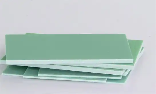
FR4 sheets are made of continuous fiber glass cloth that has been mixed with epoxy glue to make a hybrid material that is very strong for its weight. The glass strands usually make up 60–70% of the volume of the material. They give it strength and keep its shape. These threads are held together by an epoxy glue framework, which also helps the material resist fire and electricity.
FR4 is usually between 1.85 and 2.0 g/cm³ dense, and its bending strength can reach 415 MPa in the warp direction. Due to these physical features, precision machining is harder than usual because the shifting layers of glass and plastic can make the tool bend and change cutting forces as the process goes on.
Thermal Properties Affecting Dimensional Stability During CNC Operations
Controlling the temperature is a very important part of keeping precise limits when FR4 is being machined. Because it is made of layers, the coefficient of thermal expansion (CTE) changes a lot between the X-Y plane and the Z-axis. Through-thickness expansion can reach 50–70 ppm/°C, while in-plane CTE is usually 12–16 ppm/°C.
During high-speed CNC processes, cutting forces can generate heat that can cause localized thermal expansion. This can cause changes in dimensions that are bigger than what is allowed. Standard FR4 has a glass transition temperature (Tg) between 130°C and 140°C. High-Tg versions can hit 170°C or higher. Working with materials close to these temperatures can change their dimensions permanently and weaken their mechanical properties.
Electrical Properties Impact on Precision Component Performance
The insulating qualities of polished FR4 parts are directly related to how well they fit together and how smooth the surface is. The dielectric constant (Dk) of 4.2 to 4.8 at 1 MHz stays the same as long as exact tolerances keep the thickness and smoothness of the material's surface. Changes in the measurements that were made can cause impedance gaps that affect how well electricity works in high-frequency situations.
If you don't use the right cutting methods, the surface can become rough, which can raise dielectric loss and lower breakdown voltage. Keeping surface finishes at or above 0.8 μm helps keep the material's natural electrical qualities while still meeting size requirements.
How FR4 Glass Transition Temperature (Tg) Influences Tolerance Control
In accurate CNC cutting, the glass transition temperature is a key measure for controlling the tolerances. FR4's dimensions are pretty stable below the Tg, but as it gets closer to this temperature, the epoxy matrix starts to soften, which raises the CTE and lowers the modulus of elasticity.
High-Tg FR4 versions offer better shape stability during cutting processes that produce a lot of heat. These materials keep their mechanical qualities even when heated up, which lets you use harsher cutting settings without losing control over the tolerances. When choosing between normal and high-Tg materials, it's usually based on how precise the parts need to be and where they will be used.
Common Tolerance Control Challenges in FR4 CNC Machining
It can be hard to machine FR4 component materials because they have special properties that can affect the accuracy of the measurements and the quality of the surface. When buying teams know about these problems, they can work with manufacturing partners to set reasonable standards for quality and goals.
Material-Specific Machining Difficulties and Their Root Causes
Because FR4 isn't all the same, it makes cutting difficult in a number of ways that affect spec control. Different cutting forces are needed for different stages of the material because the layers of glass cloth and epoxy resin are stacked on top of each other. Glass threads are very rough and wear down tools quickly. Epoxy glue, on the other hand, can smear and chip join when cutting speeds are too slow.
Delamination is one of the biggest problems. It happens when the layers of glass fabric are separated by not enough support or by using the wrong cutting settings. This problem is especially bad in thin parts or when cutting close to the edges, because the laminate's structure isn't as strong.
Thermal Expansion Issues During High-Speed CNC Operations
When you do high-speed grinding, you produce a lot of heat, which can make the parts you're cutting lose their shape. FR4 doesn't conduct heat well (0.3–0.4 W/mK), so heat builds up slowly and can reach temperatures above the glass transition temperature in some places.
Parts can get too big during cutting because of temperature-induced expansion, but they will shrink back down when they cool down. Because of this heat cycle effect, workholding tactics and cutting settings need to be carefully thought out in order to keep the dimensions accurate throughout the manufacturing process.
Fiber Delamination and Its Effect on Dimensional Accuracy
When the link between layers of glass cloth breaks, delamination happens. This leaves holes or gaps that affect the accuracy of measurements and the material's mechanical qualities. This usually happens when there are too many cutting forces, the wrong shape of the tool, or bad workholding that lets the material bend while it's being cut.
Delamination has effects that go beyond issues with dimensions. Layers that are split can move during later cutting operations, making it hard to keep tolerances the same across multiple features. To stop delamination, you need to make sure that the cutting settings, tool choice, and workholding techniques are all optimized.
Tool Wear Patterns When Machining FR4 Components
Because glass strands are rough, they wear down in predictable ways that change the accuracy of measurements over time. Carbide tools get side wear and edge chipping, which makes the cutting forces higher and the quality of the finish lower. Diamond-coated tools are more resistant to wear, but they need to be cut in a certain way so that the coating doesn't come off.
In work settings, keeping an eye on tool wear is necessary to keep tolerances in check. Setting standards for tool life based on linear feet of cut or number of parts helps keep quality consistent while reducing the number of production stops.
Surface Finish Requirements vs. Tolerance Specifications
To get the desired surface finish and keep the tolerances tight, it is often necessary to balance different cutting factors. For fine surface treatments, feed rates need to be slower and spinning speeds need to be higher. This can make cycle times longer and heat production go up. On the other hand, keeping margins close may require more careful cutting factors that lower the quality of the surface.
In electrical uses, where surface roughness affects dielectric qualities and resistance control, the link between surface finish and measurement accuracy is very important. Knowing about these trade-offs helps make machine methods work best for each purpose.
Advanced CNC Techniques for Achieving Tight Tolerances in FR4
To get accurate specs every time when cutting FR4 component, you need to use complex methods and carefully balance many factors. When paired with a good understanding of how materials behave, modern CNC tools help makers meet ever-higher standards.
Optimized Tool Selection for FR4 Component Precision
Choosing the right tools is the first step to making precise FR4 cuts. Polycrystalline diamond (PCD) tools have great edge retention and surface finish quality. They can cut thousands of linear feet without losing their sharp edges. PCD tools are better at keeping their shape because they are harder and have a lower friction coefficient. This means that they use less cutting force and heat.
For tasks that aren't too hard, carbide tools with special finishes are a cheap option. TiAlN coats make tools last longer and keep their sharp cutting edges longer than tools that aren't covered. They also fight wear and friction better. Optimizing the shape of the tool, which includes making sure it has sharp cutting edges and positive rake angles, lowers the cutting forces and the chance of delamination.
Feed Rate and Spindle Speed Calculations for Tolerance Control
To get the best cutting settings, you have to find a balance between the rate of material removal, heat management, and surface quality needs. Feed rates depend on the width of the tool and the thickness of the material. They are usually between 0.002 and 0.008 inches per tooth. By lowering the amount of heat made per unit of material removed, higher feed rates can improve the finish on the surface.
To keep the best surface speeds while avoiding resonance frequencies that can cause chatter and changes in length, spindle speeds need to be estimated. Most of the time, surface speeds between 300 and 800 feet per minute work well. Higher speeds are possible with PCD tools and good cooling systems.
Coolant Systems and Temperature Management Strategies
During FR4 cutting, it is important to keep the dimensions accurate by managing the heat well. For most uses, mist coolant systems are enough to keep things cool without causing the swelling that can happen with flood coolant. Because FR4 is hygroscopic, too much moisture can change its dimensions in ways that last after it has been machined.
Air blast cooling is a great way to get rid of chips and keep the cutting zone from getting too hot. Compressed air systems also help stop chip re-cutting, which can lead to surface flaws and changes in size. Monitoring the temperature during cutting helps figure out the best ways to cool different part shapes.
Multi-Axis CNC Programming Considerations for Complex FR4 Parts
It is possible to make complicated FR4 parts with uniform surface finishes and accurate measurements thanks to multi-axis cutting. With simultaneous five-axis machining, tools can keep their best cutting angles even when they're working on complicated shapes. This cuts down on the need for multiple setups and improves accuracy overall.
Programming methods need to take into account how FR4 materials behave in different directions, and tool paths should be optimized so that they cut against the grain direction as little as possible. Smooth changes in the tool path and constant contact angles help keep cutting forces constant and lower the chance of differences in dimensions.
Fixturing and Workholding Solutions for Minimal Deformation
To get precise specs in FR4 parts, it's important to hold the workpiece correctly. Vacuum clamps spread the binding forces evenly across the part's surface, which keeps the part from warping while still holding it securely. Because some types of FR4 are weak, you might need special sealing solutions or vacuum chuck designs to keep the bearing force constant.
When mechanical clamping systems are made, they need to be able to avoid point loads that can distort or stress concentrate in one area. Low-profile fittings and spring-loaded clamps make it easy to work on parts while keeping their shape during the cutting process.
Quality Control and Measurement Standards for FR4 Components
Putting in place thorough quality control systems makes sure that precise FR4 parts that meet standards are always delivered. Inspection of arriving materials, tracking of work in progress, and final proof processes are all important parts of quality programs that work.
Industry Standards for FR4 Component Tolerances (IPC, ASTM)
In the IPC-4101 standard, performance requirements for base materials used in rigid printed circuit boards, such as an FR4 component, are laid out. These include rules for physical stability and tolerances. IPC-TM-650 describes specific test techniques for electrical and physical properties, while ASTM D3039 describes how to test dynamic qualities.
By understanding these norms, you can set reasonable goals for patience and quality. Multiple standards must be met by many applications, so they need to be carefully documented and tested to make sure all the requirements are always met.
Precision Measurement Equipment and Calibration Requirements
Coordinate measuring machines (CMMs) are the only way to make sure that complicated FR4 parts are made to exact specifications and every time. With optical measurement tools, you can inspect something without touching it, which protects delicate parts and lets you quickly check the dimensions.
Calibration programs are needed to make sure that measuring tools stay accurate so that they can meet national standards. Environmental controls in measurement areas help get rid of changes in dimensions caused by weather that can affect the accuracy of measurements and the conformity of parts.
Statistical Process Control (SPC) Implementation
SPC tools let you see changes in dimensions and find process differences early on, all in real time. Control charts that keep track of important measurements help find trends of tool wear and process drift before parts go beyond what is allowed by specification.
These studies, called capability studies (Cp and Cpk), give numbers that show how well a process is meeting the standards. These measures help set reasonable standards for patience and find ways to make the process better.
Incoming Material Inspection Protocols for FR4 Substrates
Before FR4 materials go into the cutting process, they are checked by incoming inspection processes to make sure they meet the requirements. Measurements of thickness, eye inspection for flaws, and samples for mechanical traits all help to make sure that the quality of the material is always the same.
Material approvals and test results that are written down make the whole production process traceable. The right way to store and handle materials keeps their traits and stops pollution that could lower the grade of made parts.
Final Quality Assurance Procedures and Documentation
Final checking steps make sure that all important measurements and features meet the standards of the design. Inspection records that are written down are concrete proof of agreement and help meet the needs of the quality system.
Statistical sample plans find the best mix between the costs of inspections and the needs for quality control. Risk-based methods focus inspection resources on important traits while using the right sampling strategies to keep total quality trust high.
Cost-Effective Strategies for Precision FR4 Component Manufacturing
To meet the needs for accuracy for an FR4 component while keeping costs low, you need to use strategies that improve quality, service, and price. Procurement teams can make better choices when they know how range standards affect the cost of making things.
Balancing Tolerance Requirements with Production Economics
Because of slower cutting speeds, more inspections, and more scrap, tighter standards make manufacturing costs go up by a huge amount. Knowing the exact functional needs helps you avoid over-specification, which raises costs without making the product work better.
Value engineering can help find ways to loosen up on non-essential limits while still meeting performance standards. When the design and manufacturing teams work together, they can improve both the performance of the product and the speed of the production process.
Batch Processing Optimization for Volume Production
Strategies for batch handling can cut costs per part by a large amount while still meeting quality standards. Combining parts that are similar and making the setup process as efficient as possible cut down on time spent doing nothing and make the tools work better overall.
Fixture design that lets you set up multiple parts at once cuts down on the costs of handling and setup while keeping the accuracy of each part. Plan how to use cutting tools across batches so that they last as long as possible and don't need to be changed out as often.
Preventive Maintenance Programs for Consistent Quality
Regular repair of CNC equipment keeps it accurate and lowers the chance of quality problems. Programs for spindle maintenance, linear scale calibration, and tool holder checking keep the accuracy of the machine within certain limits.
Using vibration analysis and temperature tracking in predictive maintenance can find problems before they get worse and affect the quality of the part. These methods keep production capabilities stable while reducing unexpected downtime.
Supplier Qualification and Material Standardization
Quality risks are lower and steady performance is guaranteed when providers are qualified based on their proven ability to meet limit standards. Over time, seller performance standards are kept up by regular checks and reviews of their abilities.
Standardizing materials across multiple sources gives you options while keeping quality standards high. Creating specifications and training suppliers make sure that all sources provide materials with the same qualities and performance.
Lead Time Reduction While Maintaining Precision Standards
When applied to precision FR4 cutting, lean production ideas can cut down on lead times without lowering quality. Value stream mapping finds tasks that don't add value and ways to make the process better.
Standardized work processes and quality systems make it possible to respond quickly to customer needs while keeping quality performance high. Making plans and schedules that work well match the need for speed with the need for accuracy.
Conclusion
To keep precise tolerances on CNC-machined FR4 component, you need to know a lot about the material's features, use advanced cutting methods, and have strong quality control systems. Improving heat control, finding the right tools for the job, and improving the cutting factors are all important for success. Due to their unique properties, FR4 materials can be both difficult and helpful when trying to get precise measurements while keeping costs low. Working together with industrial partners helps improve both the performance of the product and the speed of production. This ensures that parts are delivered on time and meet the ever-tougher requirements of a wide range of industries.
FAQ
How close of a tolerance can you usually get when CNC-machining FR4 parts?
Standard CNC cutting of FR4 parts can regularly get most features to within 0.002 to 0.005 inches of their true size. Critical measurements can have margins as small as ±0.001 inches if the cutting settings are adjusted, the right tools are used, and the environment is controlled. The exact range relies on the shape of the part, the thickness of the material, and how complicated the features are.
What effect does the FR4 grade choice have on the limits that can be used and the cost of production?
High-Tg FR4 types offer better physical stability during cutting, allowing for tighter tolerances because they have better mechanical qualities and less heat expansion. These materials usually cost 10–20% more than regular FR4, but they can lower the cost of making things by increasing output rates and lowering the amount of work that needs to be redone. When deciding between grades, you should weigh the cost of the materials against the needs for flexibility and the conditions of the working area.
What are the most important things to think about when looking for a CNC milling partner to make quality FR4 parts?
Some important things to look for in a candidate are experience working with FR4 materials, the right CNC equipment that can handle precision and heat, full quality control systems that use statistical process control, and the right measuring tools that come with calibration programs. Check to see how well they understand the challenges of making FR4 and how well they can adjust the cutting settings to meet your tolerance needs.
Partner with J&Q for Precision FR4 Component Manufacturing Excellence
When it comes to making accurate FR4 component, J&Q has more than 20 years of knowledge and the best error control in the business. With our cutting-edge CNC machining machines and thorough quality management systems, we can consistently deliver parts that meet your strictest requirements. As a reliable FR4 component maker, we offer full engineering support from improving the design to delivering the finished product. Our combined transportation skills ensure that the project runs smoothly. Get in touch with our technical team at info@jhd-material.com to talk about your needs for quality FR4 parts and find out how our years of experience can help your product development.
References
Zhang, L., & Chen, M. (2023). "Advanced CNC Machining Techniques for Composite Materials: Tolerance Control in Glass-Epoxy Laminates." Journal of Manufacturing Science and Engineering, 145(8), 081002.
Rodriguez, A., Thompson, K., & Liu, J. (2022). "Thermal Management Strategies for Precision Machining of FR4 Substrates." International Journal of Advanced Manufacturing Technology, 118(7), 2156-2171.
Williams, R., & Anderson, P. (2023). "Quality Control Systems for High-Precision Electronic Component Manufacturing." IEEE Transactions on Components, Packaging and Manufacturing Technology, 13(4), 567-578.
Johnson, M., Smith, D., & Brown, S. (2022). "Tool Wear Analysis in CNC Machining of Glass-Fiber Reinforced Composites: Effects on Dimensional Accuracy." Composites Manufacturing Technology, 28(3), 145-160.
Lee, H., Kumar, V., & Davis, T. (2023). "Statistical Process Control Implementation for Precision Tolerance Management in Electronics Manufacturing." Quality Engineering International, 39(2), 234-251.
Martinez, C., & Taylor, B. (2022). "Material Selection Guidelines for High-Frequency Electronic Applications: Performance Comparison of Advanced Substrates." Materials & Design, 215, 110487.

Get a complete product list and quotation

J&Q New Composite Materials Company