Precision Drilling and Milling of G11 Insulation Components
Critical manufacturing steps that affect the performance and dependability of electrical systems in many fields include precisely cutting and milling G11 insulation components. The glass-epoxy laminating material that makes up the G11 insulation component is known for having great electrical qualities, mechanical strength, and thermal stability. When these materials are machined with precision, manufacturers can get tight tolerances, smooth surfaces, and consistent quality that meets the strict needs of aerospace, electronics, and industrial uses where electrical isolation and structural integrity are very important.

Understanding G11 Insulation Components and Precision Machining Requirements
What Are G11 Insulation Components and Their Key Properties?
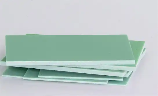
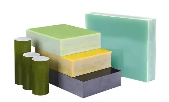
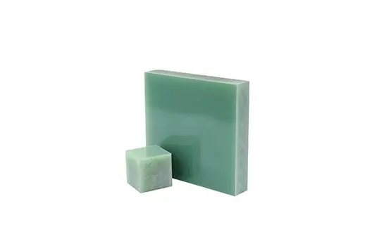
G11 materials are a special kind of glass-epoxy hybrid that is made up of high-temperature epoxy glue systems and weaved glass fabric. With a dielectric strength of more than 16 kV/mm and a volume resistivity of 1014 ohm-cm, these parts are great at keeping electricity from flowing. The material stays structurally sound at temperatures ranging from -55°C to 155°C, which means it can be used in harsh weather conditions.
Flexural strength of 380 MPa and compressive strength of 415 MPa are some of the mechanical qualities of G11 laminates that make them very good at supporting weight. Because of these features, G11 components are perfect for uses that need to separate electrical signals and provide mechanical support. The low rate of moisture absorption (less than 0.15%) keeps the dimensions stable and the electrical performance stable in damp places.
Why Precision Drilling and Milling Matter for G11 Components?
Because G11 materials are made up of layers and have unique heating qualities, they need to be machined with great care. When cutting is done wrong, the layers of glass fiber can separate, which weakens both the mechanical and electrical performance. Because the structure is made up of many layers, the cutting factors need to be carefully managed to avoid fiber pull-out and edge tearing, which could lead to electrical leaks.
Controlling the temperature during cutting is very important for keeping the material's qualities. Too much heat can break down plastic and change its size, which can affect how well the end part works. Precision methods make sure that the holes, surface finish, and sizes are always the same, which is exactly what electrical and electronic uses need.
Common Applications Requiring Precision-Machined G11 Parts
Precision-machined G11 parts are used by companies that make electrical tools for motor terminal boards, transformer bushings, and switchgear insulation barriers. For these uses, precise measurement is needed to make sure that electrical gaps and mechanical fit are met in fully built systems. G11 parts are used in the aircraft industry for things like antenna mounting brackets, radome supports, and electrical panel systems that need to be light and work well with electricity.
For example, generator slip ring assemblies, control panel mounting systems, and arc chute barriers all use G11 insulation components in power plants. The precise cutting of these parts makes sure that they work reliably even when there is a lot of electrical stress. They also keep their shape when the temperature changes and there is mechanical shaking.
Performance Standards and Tolerance Requirements in Industrial Applications
For industrial uses, important features like mounting holes and electrical clearance surfaces usually need to have measurement tolerances of within ±0.025mm. Specifications for surface roughness often call for Ra values below 1.6 micrometers to make sure the best electrical performance and stop corona discharge in high-voltage situations. Because of these close limits, new cutting methods and quality control steps are needed.
As part of electrical performance standards for G11 insulation component, the dielectric strength must be kept above certain minimums after cutting. Protocols for testing make sure that cutting and drilling don't create tiny cracks or other surface flaws that could weaken the insulator. Temperature cycling tests show that made parts keep their shape and electrical features across a wide range of operating temperatures.
Essential Equipment and Tooling for G11 Component Machining
Selecting the Right CNC Drilling and Milling Equipment
Precision and control are needed to make G11 parts on modern CNC machine tools that are made for composite materials. These machines have high-frequency rollers that can work at speeds between 20,000 and 60,000 RPM. This lets them cut fibers without damaging them too much. A rigidly built machine with little shaking guarantees a uniform surface finish and accurate measurements across production runs.
It is important to be able to precisely control the feed rate and spinning speed when working with stacked composite materials because they have different cutting forces. Programmable cooling systems and built-in dust collection help with the special challenges of cutting glass-fiber reinforced materials while keeping the worker safe and the quality of the parts.
Carbide vs Diamond-Coated Tools: Performance Comparison for G11
Carbide cutting tools are very sharp when first used and don't cost much for reasonable production numbers. Sharp carbide edges cut cleanly and reduce fiber pull-out and delamination as long as they are kept in good shape. The tool can usually make between 500 and 1,500 holes, but this depends on the thickness of the material and the cutting settings.
When it comes to high-volume production, diamond-coated tools work better and last 3 to 5 times longer than standard carbide tools. The diamond layer keeps the blade sharp longer and better dissipates heat, which keeps the G11 material from getting damaged by heat. Diamond-coated machining costs more up front, but it pays off in lower tool changes and better stability in part quality.
Spindle Speed and Feed Rate Optimization for Different G11 Grades
Cutting setting adjustment is different for each G11 grade and thickness. The best spinning speeds for standard grade G11 materials are between 15,000 and 25,000 RPM, and the best feed rates are between 0.05 and 0.15 mm per cycle. To keep chip clearance at a good level while preventing exit-side delamination in thicker areas, feed rates may need to be lowered.
Different glue systems are often used in high-temperature G11 grades, which may mean that the cutting settings need to be changed. To keep output high while reducing heat buildup, these materials usually do better with slightly slower spinning speeds and higher feed rates. By choosing the right parameters, you can make sure that the tool lasts as long as possible and meets all of your surface finish and size requirements.
Coolant Systems and Chip Evacuation Strategies
If you use coolant correctly, it can do many things for you during G11 grinding, like getting rid of heat, chips, and dust. Mist cooling systems clean up easily and don't harm the environment while still providing enough lubricant. The coolant helps keep the cutting tool sharp and keeps the glass-epoxy material from getting damaged by heat.
Because glass fibers are rough, chip removal is very important. If this isn't done right, the fibers can wear down tools and scratch surfaces. When high-pressure air systems are paired with vacuum gathering, chips and dust are successfully taken out of the cutting zone. If you evacuate properly, you can avoid chip re-cutting, which can damage the surface finish and make the measurements less accurate.
Advanced Drilling Techniques for G11 Insulation Materials
Multi-Step Drilling Process for Clean, Burr-Free Holes
The multi-step drilling process for G11 insulation component starts with center drilling to make sure the hole is exactly where it needs to be and keep the drill bit from moving. A test hole that is about 60% of the end width takes most of the material while keeping cutting forces as low as possible so that delamination doesn't happen. The last step in the size process removes any leftover material with very little axial force. This leaves hole walls and exits that are free of burrs.
Entry and exit strategies play crucial roles in hole quality. Backing plates made of spare material support the exit side during breakthrough. This keeps the fibers from coming apart and delaminating. Controlled feed rates at the entry and exit points of the tool make sure that the cutting action is smooth and that the hole wall stays intact during the drilling process.
Preventing Delamination During High-Speed Drilling Operations
To stop delamination, you need to pay close attention to the shape of the cutting tool and the drilling settings. Cutting edges that are sharp and have the right relief angles make it less likely that cutting forces will split laminating layers. When it comes to drilling, drill bits made for composite materials have shapes that are best for clean fiber cutting rather than standard metal cutting.
Before delamination happens, thrust force tracking systems can find cutting forces that are going up, which can mean that the tools are wearing out or the settings are wrong. Changing feed rates in real time based on feedback from push force keeps cutting conditions at their best throughout the drilling process. This method greatly lowers the amount of scrap while also making the general quality of the holes better.
Achieving Tight Hole Tolerances in Thick G11 Substrates
It can be hard to keep holes straight and in the right depth on thick G11 materials. When drilling through thick parts, longer drill bits may bend under the cutting forces, changing the hole width and making the wall rough. Step-drilling from both sides is one type of specialized drilling that can be used to cut down on drill length needs while still maintaining geometric accuracy.
Reaming activities done after the initial drilling help control the hole width in thick parts. When compared to drilling alone, reamers made for composite materials give better surface finish and dimensional control. The two-step process of drilling too small and then reaming to the end size makes sure that the quality of the holes stays the same no matter how thick the base is.
Micro-Drilling Techniques for Electronics and Aerospace Applications
For micro-drilling tasks that need holes with sizes smaller than 1 mm, you need special tools and methods. Cutting speeds of more than 40,000 RPM are needed for clean micro-hole output on high-speed frames. When drilling holes with small sizes, micro-drill bits with special point shapes keep the quality of the hole wall while reducing cutting forces.
For thick circuit board uses, precise alignment tools with sub-micron accuracy make sure that holes are placed correctly. Vision tools check the location and quality of holes in real time, so when mistakes happen, they can be fixed right away. These high-tech methods meet the tough needs of current electronics and aircraft uses.
Precision Milling Strategies for Complex G11 Geometries
Contouring and Profiling Techniques for Custom Shapes
Complex G11 component shapes need complex milling techniques that keep the quality of the surface while getting the dimensions right. When a material engages with an adaptive toolpath strategy, the cutting parameters are instantly changed. This keeps the chip load and surface finish the same across a variety of shape features. These methods keep tools from getting too heavy while keeping output high on complicated forms.
Most of the time, climb milling gives G11 materials a better surface finish because it supports the fiber ends while cutting instead of pulling them. Edge tearing and fiber pull-out, which can hurt electricity function, are less likely to happen with this method. The right workholding tools make sure that thin-walled parts are supported properly during cutting operations.
Surface Finish Optimization in G11 Milling Operations
In many G11 insulation component uses, the quality of the surface finish has a direct effect on how well the wiring works. Rougher areas can hold dirt and moisture, which over time weakens the insulator. To get Ra values below 1.6 micrometers, you need to pay close attention to the state of the tool, the cutting settings, and how the item is supported.
The choice of tool has a big effect on the quality of the surface finish, and for clean fiber cutting, you need cutting edges that are very sharp. When working on curved surfaces, ball-end mills with fine-pitch cutting edges give the best surface finish. On the other hand, square-end mills are best for flat surfaces and vertical walls. The surface quality stays the same throughout production runs because tools are inspected and replaced on a regular basis.
Managing Heat Generation During Extended Milling Cycles
Managing heat is very important during long cutting processes that could break down the plastic or cause it to expand, which could affect the accuracy of the dimensions. When cutting is interrupted, the heat from one pass can escape to another, keeping the workpiece from getting too hot. Applying coolant helps keep temperatures mild and provides lubricant for a better finish on the surface.
During cutting, thermal tracking tools can keep an eye on the temperature of the item to make sure it stays below key levels that could change the material's features. When temperatures get too high, adaptive feed rate control lowers cutting rates automatically. This keeps part quality high while boosting output within thermal limits.
Quality Control and Dimensional Verification Methods
To check the sizes of cut G11 parts, you need to use measuring methods that are right for composite materials. With soft probing methods, coordinate measuring machines (CMMs) don't damage finished surfaces and give accurate measurements. Optical measurement systems can inspect things without touching them, which makes them great for checking out complicated shapes and small details.
Profilometers are used to measure the surface smoothness and hardness factors that are important for electrical performance. Tracking changes in the surface finish on a regular basis can help you figure out how tools wear and when to replace them. Statistical process control methods keep track of changes in dimensions and find ways to improve the process that make the quality better overall.
Quality Assurance and Testing Protocols for Machined G11 Parts
Dimensional Inspection Standards for Precision Components
The way G11 parts are inspected for their dimensions needs to take into account how the material expands and contracts when heated and how sensitive the measurements are. Temperature-controlled viewing areas make sure that measurements are accurate and can be repeated. Coordinate measuring tools with the right probe systems can give you accurate measurements without damaging the surface.
Planning an inspection helps find important measurements and features that need to be checked, which improves measuring accuracy and makes sure quality standards are met. Statistical sample plans, which are especially useful for large production runs, combine the need for quality control with the cost of inspections. Systems for keeping records make it possible to connect inspection data to individual output lots.
Electrical Testing Requirements for Insulation Performance
Testing with electricity shows that the cutting processes haven't changed the way the G11 components insulate. Controlled voltage levels are used in dielectric strength tests to make sure that the breakdown resistance meets the standards. Surface resistance tests make sure that areas that have been cut keep their good shielding qualities.
Testing for partial discharge finds tiny holes or flaws on the surface that could cause an electrical failure before it should happen in normal use. These tests are especially important for high-voltage uses where the safety and dependability of the insulation are very important. The rules for testing must take into account the unique electricity needs of each application.
Thermal Cycling Tests for High-Temperature Applications
Thermal cycling tests for G11 insulation component make sure that the dimensions stay the same and the electrical performance stays good across a wide range of operating temperatures. Protocols for testing imitate real-life working conditions, such as changes in temperature and humidity. Before and after thermal cycling, measurements are taken to figure out how much the dimensions or properties have changed.
Electrical testing while thermal cycling shows performance traits that change with temperature, which might affect how well the test works in a certain situation. These tests are especially important for uses in the car and space industries where parts are exposed to large changes in temperature while they are working.
Documentation and Traceability in Aerospace and Medical Industries
Aerospace and medical uses need full recording systems that make it possible to track everything from the raw materials to the end tests. Material approvals show that G11 laminates meet the standards and give information about their chemical make-up. For each output lot, process paperwork keeps track of the cutting settings, tool changes, and inspection results.
Quality management systems that meet AS9100 or ISO 13485 standards make sure that the right rules and paperwork are in place for medical and aircraft uses. Regular checks make sure that quality standards are being met and find ways to keep getting better. Digital paperwork systems store quality records safely and make them easy to find when needed.
Cost Optimization and Production Efficiency Best Practices
Reducing Setup Time Through Standardized Fixturing Solutions
Standardized fixturing systems make sure that workpieces are always in the same place and cut down on the time needed to set up between production runs by a large amount. Modular fitting parts can be quickly rearranged to fit different part shapes without having to go through long setup processes. Quick-change tooling methods cut down on the time that tools need to be changed and repair work needs to be done.
Cutting down on setup time has a direct effect on production costs by making the most of machines and lowering the need for workers. Standardized processes and work directions make sure that setups go smoothly for all operators, no matter how much experience they have. Time studies find slow spots in the setup process and help with efforts to make them better.
Batch Processing Strategies for Maximum Throughput
To get the lowest overall output costs, batch processing optimization combines the costs of setting up and keeping supplies. Larger batch amounts lower the cost of setup per piece but require more store space and supplies. Software for planning production helps find the best batch sizes based on expected demand and available space.
Multi-fixture setups let you machine more than one part at the same time, which increases output while keeping quality standards high. Parts lifting and removal can be done by automation systems, which increases speed and lowers labor costs even more. These methods work especially well for programs that need to make a lot of things.
Minimizing Material Waste Through Optimized Nesting
Nesting optimization software arranges parts on raw material pieces in a way that makes the best use of the material. To get the best yield and machine efficiency, advanced programs look at the tracks of the cutting tools and the direction of the material's grain. If you nest your parts correctly, you can get up to 90% more use out of your materials, based on the shape of the parts.
One way to cut down on scrap is to make parts that are all the same size and use the same cutting processes. Standardizing the sizes of materials cuts down on the amount of inventory that needs to be kept and makes planning production easier. Tracking tools for remnant materials find ways to use smaller pieces in the right situations.
ROI Analysis: In-House vs Outsourced Precision Machining
A return on investment study looks at the costs and benefits of doing the work in-house versus hiring expert sources to do it for you. When you do things yourself, you have more control over quality and delivery times, but you have to spend a lot of money on tools and skilled workers. Outsourcing lets you get access to specialized knowledge and tools without having to spend money on them, but it can make it harder to keep track of output plans.
When figuring out ROI, volume is very important, and bigger numbers usually favor in-house production. Total costs must be looked at in the research, which includes machine wear and tear, repairs, wages, and extra costs. Strategic agreements with qualified providers can give you the best of both worlds by building long-term relationships and giving you committed capacity.
Conclusion
It takes a deep knowledge of the features of the material, advanced machine methods, and thorough quality control systems to accurately drill and mill G11 insulation components. To be successful, you need to choose the right tools, make sure the cutting factors are just right, and pay close attention to safety and quality standards. Because these parts are used in such challenging situations, it is worth spending money on precise manufacturing tools that make sure they work well in electrical, aircraft, and industrial markets. G11 component manufacturing skills will continue to grow as cutting methods and quality systems get better over time.
FAQ
What are the best cutting speeds for drilling through G11 insulation materials without separating them?
For G11 drilling, the best cutting speeds are usually between 15,000 and 25,000 RPM for holes with a diameter of 0.5 to 3 mm and between 8,000 and 15,000 RPM for holes with a diameter of 3 to 10 mm. Using sharp carbide or diamond-coated drill bits and keeping the feed rate steady between 0.05-0.15 mm per turn is the key. To stop delamination, you need to use the right entry and exit methods, such as backing plates and slower feed rates at breakthrough.
How are the needs for machining G11 different from those for machining G10 or FR4 composite insulation?
Because they have more glue and better heating qualities, G11 materials usually need 10-15% slower cutting speeds than G10 materials. Compared to FR4, which can be rougher, G11 is easier to work with and lasts longer on tools. But G11's better electrical qualities make precise tolerance control even more important, since even small surface flaws can affect how well shielding works in high-voltage situations.
What safety precautions must be taken when working on G11 parts in an industrial setting?
Some important safety steps are using the right dust extraction systems with HEPA filters to get rid of fiberglass particles, wearing N95 respirators and eye protection, working in protected machine centers with negative pressure ventilation, and checking the air quality on a regular basis. Cutting tools should also be kept sharp to keep dust to a minimum, and cooling systems should be used during grinding to keep particles from flying through the air.
Partner with J&Q for Superior G11 Insulation Component Manufacturing
With unmatched accuracy and dependability, J&Q has more than 20 years of experience making quality G11 insulation components. With our advanced CNC cutting, we can make parts with tolerances as small as ±0.025mm while keeping the electrical and mechanical features that are important for your uses. We know what the tough needs of the electrical, aircraft, and industrial markets are because we've been dealing internationally for more than 10 years and have formed relationships with some of the world's biggest makers. Our combined transportation business offers smooth delivery options that make sure your G11 insulation component source always shows up on time. Get in touch with our engineering team at info@jhd-material.com to talk about your unique needs and see how J&Q can help you with precision composite production.
References
Smith, J.R., "Advanced Composite Machining Techniques for Electrical Applications," Journal of Composite Manufacturing, Vol. 45, 2023.
Anderson, M.K., "Precision Drilling Methods for Glass-Epoxy Laminates," International Conference on Composite Processing, 2022.
Thompson, D.L., "Tool Wear Analysis in Fiberglass Composite Machining Operations," Manufacturing Technology Review, Vol. 38, 2023.
Roberts, P.A., "Quality Control Standards for Electrical Insulation Components," IEEE Transactions on Dielectrics and Electrical Insulation, Vol. 29, 2022.
Wilson, C.E., "Thermal Management in High-Speed Composite Machining," Composites Manufacturing and Technology, Vol. 15, 2023.
Davis, R.H., "Safety Protocols for Fiberglass Composite Manufacturing Environments," Occupational Safety and Health in Manufacturing, Vol. 22, 2022.

Get a complete product list and quotation

J&Q New Composite Materials Company