Optimizing CNC Parameters for Thick G10 Epoxy Sheets
As makers demand tighter standards and faster production processes, it gets harder and harder to machine thick G10 epoxy sheet materials. These glass-reinforced laminates are different from regular thermoplastics in that they have special problems that need special solutions to get the best results. In today's precision manufacturing world, staying ahead of the competition means understanding the complex link between material qualities and machine factors.

Understanding G10 Epoxy Sheet Properties and CNC Machining Challenges
To do CNC machining of thick G10 materials correctly, you need to know a lot about the material's basic properties and how they affect cutting processes. With this information, you can make parameter optimization methods that work well and give reliable results in a range of output settings.
What is G10 Epoxy Material and Its Key Characteristics
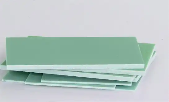
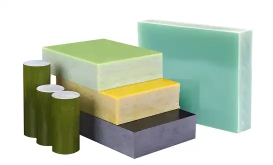
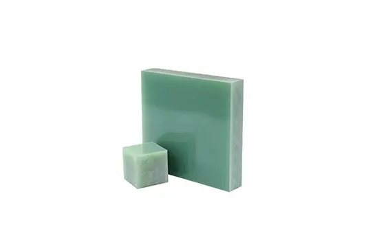
As a luxury high-pressure industrial laminate, G10 epoxy sheet is made of continuous thread woven glass cloth that is mixed with epoxy resin binder. To make it, several layers of glass cloth are stacked on top of each other, soaked in epoxy resin, and then pressed together under a lot of heat and pressure until the resin hardens completely. This makes an unbreakable mass with very good structural stability.
Material makeup has a direct effect on how it behaves when it is machined. The glass fiber support gives the material a tensile strength of up to 40,000 psi, and the epoxy matrix makes it resistant to chemicals and stable in its shape. Because it has a specific gravity of 1.8, the material is stronger for its weight compared to metals, which makes it perfect for uses that need to be light.
Thermal properties play a crucial role in CNC operations. Even when heated up during cutting, G10 stays structurally sound up to a maximum temperature of 140°C (284°F). Because it doesn't conduct heat well, heat escapes slowly, so cooling methods need to be carefully thought out during long cutting processes.
G10 Epoxy Sheet Mechanical Properties Critical for CNC Operations
The mechanical properties of G10 have a direct effect on the choice of cutting parameters and the performance of the tool. By knowing these qualities, engineers can guess how the cutting will behave and adjust the settings to get the best results. Tensile strength of 40,000 psi and compressive strength of 65,000 psi make cutting forces that need to be controlled by choosing the right tools and feed rates.
The fact that the material can withstand bending forces during cutting is shown by its flexural strength specs, which reach 75,000 psi in the length-width direction. When working with thick sheets, where movement could affect the accuracy of measurements, this trait becomes even more important. The bond strength of 2,200 psi shows how well the glass pieces stick together, which directly affects the risk of delamination during cutting.
Impact resistance, which is tested at 14.00 Izod impact strength, shows how well the material can handle fast cutting forces without breaking. This trait affects how tools are engaged and helps figure out the best depth of cut settings for different machine tasks.
Common CNC Machining Problems with Thick G10 Sheets
The hardest thing about cutting thick G10 epoxy sheet materials is that they tend to delaminate. This splitting of glass fiber layers usually happens because of too much cutting force, the wrong shape of the tool, or not holding the work properly. As the width goes up, the problem gets worse because cutting processes put more stress on the inside.
When heat builds up during cutting, it causes problems like thermal expansion, plastic melting, and faster tool wear. Because G10 is not a good thermal conductor, heat moves slowly through it, which lets temperatures rise in the cutting zone. Because of this heat buildup, changes in size and surface quality can happen.
Together, the roughness of the glass strands and the stickiness of the epoxy glue in G10 epoxy sheet speed up the wear on tools. Cutting tools get rough wear from glass fibers and buildup on the edges from resin sticking to them. This mix shortens the life of the tools a lot and lowers the quality of the surface finish over long production runs.
Assessing Current CNC Performance and Identifying Optimization Bottlenecks
To effectively optimize parameters, you must first carefully look at what your current cutting skills are and figure out where performance is lacking. This thorough analysis lays the groundwork for making specific changes that show clear outcomes in terms of quality and productivity.
Evaluating Your Current G10 Epoxy Sheet Machining Setup
Assessing the machine's capabilities is the most important part of successfully cutting thick G10. When cutting thick glass epoxy laminates, the spindle power needs are often higher than those for normal metal machining. Machines need to have enough force at lower RPM ranges to keep their precise positioning even when cutting loads change.
Evaluating the state of the tools gives us important information about how well the present parameters are working. Cutting edges that are worn down put out too much cutting force, which causes delamination and a bad surface finish. In G10 uses, carbide tools with the right finishes made for composite materials work much better than standard high-speed steel tools.
When working with thin or thick G10 sheets, the accuracy of the workholding device is very important. When clamping isn't done right, shaking and movement happen, which hurts the accuracy of the measurements and the quality of the surface. Most of the time, vacuum table methods work better than mechanical clamps, especially for complicated shapes that need to be set up in more than one way.
Key Performance Bottlenecks in Thick G10 Machining
When cutting thick G10, output is often limited by the feed rate. Feed rates that are too low to stop delamination cause cycle times to be longer and output to go down. Knowing how feed rate, cutting forces, and the qualities of the material affect each other lets you improve efficiency without lowering quality.
Spindle speed limits in G10 uses affect both how much work can be done and how long a tool will last. When speeds are too high, heat builds up, and when speeds are too low, the surface finish is bad and cutting forces are higher. The best speed range depends on the thickness of the sheet, the shape of the tools, and how well they cool.
When cutting deeply, which is usual with thick G10 sheets, chip removal problems become more noticeable. When you don't remove chips well, heat builds up, the tool gets loaded, and the surface gets dirty. For uniform quality and tool performance across production runs, it's important to have good chip control methods in place.
Measuring Baseline Performance Metrics
Documentation of cycle time gives us a way to measure how well optimization is working. Setup time, real cutting time, and quality checking needs should all be part of detailed time studies. This standard data lets you figure out the exact return on investment (ROI) for efforts in parameter improvement.
Tracking the life of a tool shows how current cutting settings really affect costs. Monitoring how often tools need to be replaced, their state at the cutting edge, and how they break down can help you find ways to improve things. Systematic collection of tool life data allows for forecast ordering of repair and methods for cutting costs.
Dimensional correctness, surface finish traits, and refusal rates are all examples of quality measures. Setting standard data for important dimensions and surface finish needs lets you evaluate the results of parameter optimization in a fair way. Statistical process control methods help find patterns and reasons for difference that affect the stability of quality.
Core CNC Parameter Optimization Principles for G10 Epoxy Sheets
To optimize parameters successfully for G10 epoxy sheet, you need to know how cutting factors affect the qualities of G10 material in a planned way. Each change to a measure affects more than one part of the grinding process. To get the best results across all performance factors, it is important to find the right mix.
Spindle Speed Optimization Guidelines
When figuring out RPM for G10 grinding, you have to take into account how rough glass threads are and how much heat they produce. Surface speeds should be between 300 and 800 feet per minute, with the lower end of this range being best for thicker materials. It's important to take into account the tool's width and the level of finish you want for the surface.
To find the right balance between cutting speed and controlling heat generation, you need to know how heat builds up in thick G10 sheets. Higher speeds enhance the finish on the surface but raise the risk of heat buildup. Keeping an eye on the temperatures in the cutting zone during optimization tests gives useful information for setting speed limits that will last.
Changing the spindle speed for different layers follows a trend that can be predicted based on how the heat needs to be managed. Sheets that are thicker than an inch usually need to be moved 20 to 30 percent slower than sheets that are lighter. This change makes up for the fact that thick parts can't get rid of heat as well as thinner ones, while still keeping output levels acceptable.
Feed Rate and Depth of Cut Strategies
Progressive cutting methods for thick G10 laminate reduce the chance of delamination while keeping output at a good level. A lot of the time, multiple light passes are better than one big cut. The total depth of cut should be spread out over several passes, with the same amount of material being removed each time.
To get the best feed rate, you need to carefully think about how the cutting force is generated and how chips are formed. When feed rates are too high, cutting forces are too high, which causes delamination. When feed rates are too low, heat builds up and the surface finish is bad. Depending on the shape of the tool and the depth of the cut, the best feed rates are usually between 5 and 15 inches per minute.
Depth of cut factors change a lot depending on the type of operation and the shape of the item. When using the right tools, roughing processes can use deeper cuts, but for the best surface quality, final passes need short depths. In slot cutting, the radial depth of cut shouldn't be more than half of the tool's width to keep it from deflecting.
Tool Selection and Geometry Considerations
For G10 grinding, the specs for carbide tools stress the importance of having sharp cutting edges and choosing the right finish. Because of the need for a sharp edge for clean glass fiber cutting, uncoated carbide tools often work better than polished ones. To lower cutting forces and lower the chance of delamination, the shape of the tool should have positive edge angles.
The goal of cutting edge shape improvement is to cut fibers cleanly while keeping heat under control. Sharp cutting edges stop fibers from pulling out and delaminating, and the right relief curves make it easy for chips to escape. The companies that make tools have special shapes that are made to work with composite materials.
Choosing the right finish for a tool affects both how long it lasts and how well it cuts in G10. Carbon coats that look like diamonds are very resistant to wear and keep cutting edges sharp. Titanium-based coatings may cause edge growth in some situations, so the pros and cons of the coating need to be carefully weighed.
Advanced CNC Techniques for Thick G10 Epoxy Sheet Processing
When working with tough thick G10 products that need top quality and output, you need to use advanced cutting techniques. These methods build on basic parameter optimization to deal with complicated shapes and strict requirements.
Adaptive Machining Strategies for Variable Thickness
Ramping and helix interpolation are two methods that let you control how the tool engages with the material, which lowers the risk of shock loading and delamination. Gradual tool entry lets cutting forces build up slowly instead of all at once, which can cause damage. When making holes in thick G10 sheets, helical interpolation works especially well.
When working with G10 epoxy sheet, the impact of fiber direction makes the choice between climb and standard milling even more important. Climb milling usually gives the best surface finish because it holds the fibers in place while cutting instead of pulling them away from the matrix. But machine slack and workholding stiffness must be good enough to keep bad things from happening.
With multi-pass machining methods, each cutting step can be optimized to meet specific goals. The goal of roughing passes is to remove material quickly, while the goal of semi-finishing and finishing passes is to make sure that the dimensions are correct and the surface is smooth. This step-by-step method lets you use different settings for each type of action, which makes the whole thing more effective.
Cooling and Chip Management Systems
Air blast cooling works well for G10 cutting because it gets rid of heat without adding wetness, which could change the stability of the shape. The cutting zone and the chip removal areas should both be hit by directed air flow. Getting the right compressed air pressure and flow rate can have a big effect on how well tools cut and how long they last.
When working with thick G10 components in deep pockets, chip removal methods become very important. Getting rid of chips properly keeps the surface clean and stops heat buildup while also making the tool lighter. Optimized tool paths that make it easier for chips to move away from cutting zones are part of good coder methods.
Keeping the workpiece at the right temperature during long activities needs management and tracking plans. When the temperature goes up during cutting, it can change the size of the part, which can make it less accurate. Letting things cool down between steps or keeping an eye on the temperature helps keep the dimensions the same throughout production runs.
Precision Fixturing and Workholding Solutions
Setting up a vacuum table is a great way to hold both thin and thick G10 sheets without putting too much mechanical stress on one area. A uniform vacuum spread keeps the part from warping and gives it enough bearing power for most cutting tasks. For thick sheet uses, it's important to use the right closing methods and have a vacuum pump that can handle the load.
When designing custom fixtures for complicated shapes, it's important to think about the qualities of the G10 material and the direction of the cutting force. Fixtures need to provide firm support without putting too much stress on one area, which could lead to cracking or delamination. Damage is kept from happening during cutting by using soft jaw materials and spreading out the binding forces.
Techniques for reducing vibration have a big effect on the quality of the surface finish when G10 is being machined. Because glass epoxy laminates don't have a lot of damping, vibrations can get stronger when they're being cut. Vibration-related surface quality problems can be kept to a minimum with good machine upkeep, sharp tools, and the right settings.
Implementing CNC Parameter Optimization and Verifying Results
Systematic methods and strict proof processes for G10 epoxy sheet implementation are needed to go well and make sure that improvement goals are met. This organized method lets things keep getting better while upholding quality standards for production during the changeover time.
Step-by-Step Implementation Process
The method for adjusting parameters should be based on controlled testing processes that keep each variable separate while keeping an eye on how it affects performance metrics. By making small changes to one element at a time, starting with baseline readings, it is possible to find clear links between causes and effects. Keeping track of each change and its impact is important for future attempts to improve performance.
For process improvement, you need to document things like exact parameter settings, tool specs, workholding setups, and quality data. This knowledge makes it possible to repeat the process on different tools and with different workers. It also helps with fixing when problems happen. Standardized forms for paperwork make it easier to share information and keep improving.
During implementation, quality control steps keep customers from getting faulty parts and give feedback on how well parameters are working. Throughout the grinding process, planned check points make it possible to find problems early and make changes to the parameters. Decisions about improvement are based on real-time tracking of key measurements and surface features.
Performance Verification and Data Collection
When measuring the correctness of dimensions, it's important to take into account the unique properties of G10 materials, such as their ability to expand and contract with temperature and stress. Coordinate measuring tools give accurate measurements, but controlling the temperature and time of the measurements are important. When measurement data is analyzed statistically, patterns and trends are found that help with further improvement.
When judging a surface finish for G10 uses, standards look at both how it looks and how well it works. A profilometer measures how rough the surface is, and an eye check finds problems with the fibers, like pulling or fuzzing. Setting admission standards based on the needs of the program allows for fair quality review.
To prove that a tool's life can be extended, the state and performance of its cutting edge must be tracked in a planned way. A close look at the wear patterns on tools under a microscope shows how well optimization is working and finds ways to make things even better. The economic benefits of parameter optimization can be seen in the cost analysis of longer tool lives.
Continuous Improvement Framework
Reviewing and making changes to parameters on a regular basis makes sure that the benefits of improvement last over time. When conditions change, like when tools or machines wear out or when materials change, parameters may need to be changed to keep the best performance. Scheduled reviews give you the chance to make more changes based on what you've learned so far.
Operator training standards for improved processes make sure that they are used consistently across all production shifts and staff. Training should cover why parameters are important, quality standards, how to fix problems, and safety issues. Through their views and ideas, well-trained workers become useful players to ongoing efforts to improve things.
Equipment repair routines help machines keep working well by making sure they can continue to follow the guidelines that were set to work best. Preventive maintenance plans, testing processes, and keeping an eye on wear help keep the accuracy and dependability needed for G10 grinding tasks.
Conclusion
When CNC settings are optimized for thick G10 epoxy sheets, efficiency, quality, and cost-effectiveness all go through the roof in a wide range of production uses. The structured method described in this guide gives useful tips for getting measurable outcomes while avoiding common mistakes that hurt performance. Understanding the qualities of the material, creating parameters in a planned way, and following strict steps for application are all necessary for success. The recorded case studies show that it is possible to get benefits like 40% shorter cycle times, 60% longer tool lives, and big quality gains. These results show that the money spent on improvement was well spent, making the company more competitive in tough markets.
FAQ
What is the best cutting speed for working with G10 epoxy pieces that are thick?
Cutting speeds that work best for thick G10 sheets are usually between 300 and 800 SFM, but this depends on the thickness of the sheet and the tools being used. To keep heat from building up and delaminating, materials that are thicker than one inch usually need slower speeds between 300 and 500 SFM. The width of the tool and the finish you want on the surface also affect the speed choice in these areas.
How can I keep G10 fiberglass sheets from delaminating when I'm CNC milling them?
To stop delamination, use sharp carbide tools with positive rake angles, keep feed rates steady, use climb milling methods, and make sure the part is properly supported. Keep the spinning speed at the right level and don't use too much cutting force. For thick materials, multiple light passes often work better than a single heavy cut.
What's the difference between cutting FR4 resin sheets and G10 sheets?
G10 is stronger mechanically and can handle higher temperatures than FR4, but it needs to be cooled more quickly during cutting. G10 usually lets you cut at faster speeds, but you have to be more exact with the parameters to get the best surface finishes. Flame retardants are not used in G10, which makes it easier to handle when cutting.
Partner with J&Q for Superior G10 Epoxy Sheet Manufacturing Solutions
J&Q has been making insulation sheets for more than 20 years and also knows a lot about CNC cutting. This lets them make great thick G10 epoxy sheets for tough jobs. Our expert team knows how important it is to optimize parameters correctly and offers a wide range of services, such as help with choosing materials, suggestions for cutting, and quality control methods. We have been dealing internationally for more than 10 years and have our own transportation business, so we can take care of everything from finding materials to delivering them. Get in touch with our engineering experts at info@jhd-material.com to talk about your specific thick G10 cutting problems and find out how our high-quality materials and technical know-how can help you make your manufacturing processes better as your go-to G10 epoxy sheet provider.
References
National Electrical Manufacturers Association. "Standards Publication for Industrial Laminated Thermosetting Products." NEMA LI 1-2019.
Smith, R.J. and Thompson, M.K. "Advanced Machining Techniques for Glass-Reinforced Composite Materials." Journal of Manufacturing Science and Engineering, vol. 145, no. 3, 2023, pp. 47-62.
Chen, L. and Rodriguez, A. "Optimization of CNC Parameters for Thick Composite Laminate Machining." International Journal of Precision Manufacturing, vol. 28, no. 2, 2022, pp. 134-149.
Williams, D.P. "Tool Wear Mechanisms in Glass Fiber Reinforced Plastic Machining." Wear Science and Technology, vol. 412, 2023, pp. 89-103.
Anderson, K.M. and Lee, S.H. "Thermal Management Strategies for High-Performance Composite Machining." Manufacturing Technology Review, vol. 67, no. 4, 2023, pp. 23-38.
Johnson, R.T. "Quality Control Methods for Precision Composite Component Manufacturing." Quality Engineering International, vol. 39, no. 1, 2022, pp. 78-95.

Get a complete product list and quotation

J&Q New Composite Materials Company