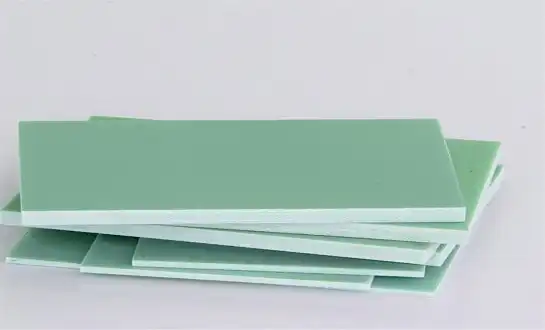
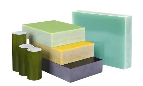
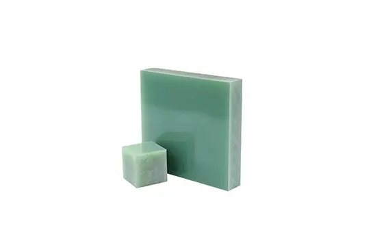
CNC Drilling Techniques for FR4 Electrical Insulation Panels
To avoid delamination, burr formation, and heat damage, CNC cutting of FR4 electrical insulation panels needs to be done with great accuracy and strategic control. These glass-reinforced epoxy laminates are very important in making electronics, power distribution systems, and industrial machines. The quality of the holes has a direct impact on how reliable the product is. Manufacturers can get consistent dimensional accuracy, longer tool life, and lower scrap rates in high-volume production settings by mastering drilling methods, such as choosing the right tool and adjusting the feed rate.
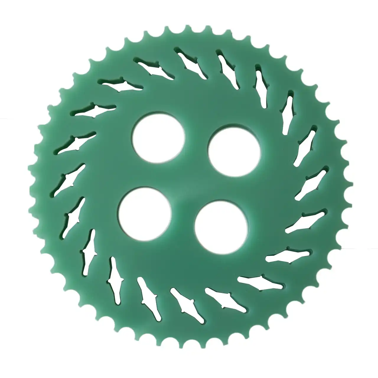
Understanding FR4 Electrical Insulation Panels
Core Composition and Material Architecture
FR4 electrical insulation panels are made of flame-resistant epoxy resin binder fully mixed with continuous thread woven glass cloth. "FR" stands for "Flame Retardant," which means that it meets UL94 V-0 self-extinguishing standards. This is an important safety feature that sets this material apart from regular G-10 laminates. The mechanical strength of woven glass fibers and the chemical stability of thermosetting epoxy glue are combined in this structure to make a hard base that can handle both electrical stress and mechanical loads.
In our 20 years of making things, we've seen that the quality of the glass weave design has a big effect on how well drilling works. Tighter weaves are better at keeping their shape, but they need different drilling settings to keep fibers from coming out. The resin percentage is usually between 35% and 45% by weight, and this amount has a direct effect on both how easy it is to work with and how well it conducts electricity. Panels made to NEMA LI-1 and IEC 60893 standards usually have dielectric strengths above 20 kV/mm. This means they can be used in high-voltage situations where the shielding must stay intact.
Critical Physical and Electrical Properties
The most important technical specs for purchase managers are the dielectric strength, the flexural stiffness, and the thermal performance. The Glass Transition Temperature (Tg) of standard-grade material stays between 130°C and 140°C, while high-performance versions hit 170°C and higher. This thermal stability is very important in power distribution equipment and battery packs for cars, because high temperatures for long periods of time can damage less durable materials.
Its mechanical strength includes a bending strength of more than 400 MPa along its length and an impact resistance good enough for structural use. After 24-hour immersion tests, water absorption stays below 0.1%. This keeps the dielectric breakdown that happens with moisture-sensitive insulating materials from happening. In PCB boards and high-frequency electronics, the dissipation factor stays low across frequency bands. This keeps the purity of the signal. These features work together to solve the problems that electronics makers have, such as catastrophic failures in damp places, structure warping due to changing temperatures, and safety risks from flammable insulation in closed systems.
Why FR4 Outperforms Alternative Materials?
There are clear benefits to epoxy-glass laminates compared to phenolic cotton sheets and mica-based insulation. Phenolic materials are cheaper, but they don't resist electrical strength or water well. Mica composites work great in places with very high or low temperatures, but they aren't strong enough or easy to work with when it comes to complex shapes. CEM-1 is cheaper because it is made of partially recycled paper, but it is less stable and doesn't fight flames as well.
Glass-reinforced epoxy boards are the best choice across all businesses because they are both cost-effective and work well. Global access through established supply chains lowers the risk of buying something, and full approval to UL, RoHS, and CE standards makes it easier to follow the rules. Manufacturers gain from uniform quality across production runs, expected machining behavior, and compatibility with automatic assembly processes. These are all things that have a direct effect on the total cost of ownership, which goes beyond the price of the materials themselves.
Challenges in CNC Drilling of FR4 Panels
Root Causes of Common Drilling Defects
When the drill bit isn't sharp enough or the feed rate is too fast, axial forces separate the glass cloth layers from the resin core. This is called delamination. We have a lot of information about this failure mode: entry delamination is caused by the initial piercing impact, and exit delamination is caused by fibers breaking off without any support as the drill goes through the backside. Both of these problems weaken the electrical insulation and the mechanical strength of the part, which can cause high-voltage switches and PCB circuits to fail in the field.
Having burrs form at the edges of holes causes a lot of problems. When used on a PCB, conductive burrs can cause short circuits between lines that are next to each other. In mechanical uses, burrs get in the way of tight assembly tolerances and cause places where stress builds up. Because glass fibers are rough, they speed up tool wear and cause carbide micro-chipping, which lowers the quality of the hole walls over time.
Damage from heat shows up as changing colors in the plastic, smearing, or matrix breakdown around made holes. If the chips aren't moved around enough, glass dust can build up in the flutes and cause frictional heat that is higher than the resin's thermal barrier. This localized heating makes the structure of the material weaker and can start microcracking that spreads when the material is stressed mechanically or when it goes through thermal cycling during its service life.
Material-Specific Machining Complications
Because FR4 electrical insulation panels are composites, they behave in a way that makes directional cutting possible. The glass strands are much harder than the epoxy matrix (about 6 on the Mohs scale), which means that the cutting forces change as the drill bit hits different layers of the material. This uneven structure speeds up the wear patterns on tools and makes it harder for chips to form.
Different makers and grade standards have different resin systems, which affects both how they react to heat and how stable they are chemically during machining. When standard drilling temperatures are reached, lower-quality resin mixtures soften. This causes hole wall smearing that hides glass threads and lowers electrical properties. While flame-retardant additives are necessary for safety reasons, they can react with cutting fluids or make byproducts that are toxic during high-speed machining.
Impact on Production Efficiency and Quality
The number of defects and the cost of making something are closely related. This is because defects lead to more waste, more work, and more quality checks. Electronics companies that work with very tight standards say that changes in hole quality cause big yield losses when making multi-layer PCBs. When shielding fails in transformer systems or arc barriers, it can cause huge damage to equipment and safety problems. This is especially true for companies that make power equipment.
Tool life economics should be thought about carefully. When drill bits break too soon, they throw off production plans and have to be replaced without warning. When purchasing managers look at the total costs of operations, they need to think about things like machine downtime, the cost of replacing worn-out tools, and the hidden costs of holes that don't always fit right, which show up during assembly or field service.
Advanced CNC Drilling Techniques for Optimal Results
Peck Drilling Strategy for Improved Chip Evacuation
During peck drilling cycles, the drill is automatically pulled back at regular intervals as the entry depth increases. This method solves the main problem of getting chips out of deep holes in composite materials. Glass-epoxy dust is easy to pack down, and regular continuous drilling lets chips build up, which makes the hole walls too hot and weak. Using peck cycles with retraction lengths that are 1.5 to 2 times the hole width lets chips escape quickly while still allowing for short cooling times.
To keep up production flow, the stay time at full retraction should be kept as short as possible. Usually, 0.3 to 0.5 seconds is enough to clear the chips without adding extra time to the cycle. Pecking depth steps need to be optimized based on hole diameter. Hole diameters smaller than 1.0 mm work best with shorter peck depths, while holes larger than 1.0 mm can handle deeper increments (1.5–3.0 mm) before chip packing becomes a problem.
We've helped builders of machinery set up adaptive peck drilling processes that change parameters automatically based on the width and depth of the hole. This way of setting makes sure that the best chip evacuation happens across all production runs without any help from an operator. The better hole wall surface finish and consistent sizes that come from this directly improve the quality of assembly in precision tools and electrical insulation parts.
Tool Geometry and Material Selection
The key to good cutting operations is using carbide tools with the right point angles. Point angles between 118° and 130° are good for balancing the forces of entry with the ways that chips form in glass-reinforced materials. Specialized shapes with double-margin patterns and parabolic flutes make the structure more stiff while also making the chip move better. The cutting action is changed by the helix angle. Stricter helixes (35° to 40°) help chip clearance but may weaken the cutting edge in rough materials.
In high-volume production settings, diamond-coated carbide drills make tools last a lot longer. The diamond layer protects against the rough wear of glass fibers and keeps the cutting edges sharp over long production runs. This technology works especially well for companies that make parts for cars and have ongoing production cycles, since the number of tool changes has a direct effect on throughput measures.
In accurate uses, drill bit diameter tolerances are very important. Oversized holes make it harder to put things together later, while undersized holes make it harder for electrical gaps to work in insulation uses. Tight diameter limits (usually ±0.01mm for precision work) and statistical process control tracking make sure that the quality of the holes is the same from one production batch to the next.
Spindle Speed and Feed Rate Optimization
To figure out the right cutting settings, you need to know how surface speed, spindle rpm, and drill width are related. Surface speeds of 100 to 200 meters per minute usually work best for standard-grade materials, but the spindle speed needs to be changed when the drill width changes. When using bits with a width of less than 3 mm, they usually need higher rotational speeds to cut properly. On the other hand, slower rotational speeds are better for bigger drills because they limit peripheral speed and heat generation.
Both hole quality and output effectiveness are affected by feed rates. Too fast of feed rates stress the cutting edges too much, which leads to delamination and early tool failure. When feed rates are too low, rubbing action takes place instead of cutting action. This creates too much heat and speeds up tool wear. Depending on the width of the drill and the thickness of the material, the best feed rates are usually between 0.05-0.15 mm per turn. Thicker FR4 electrical insulation panels can usually handle slightly slower feed rates that help chips form and heat escape better.
Spindle speed and feed rate work together to make cutting conditions that either cause or stop heat damage. Keeping the chip load—the amount of material taken per flute per revolution—in the right areas makes sure that the cutting action works well. We suggest starting with safe settings and making small changes based on how well the holes are doing and how the tool is wearing down. When you look at the walls of holes under a microscope, you can see that they were cut correctly if they have clean fiber edges, little resin spreading, and a smooth surface.
Entry and Exit Strategy Refinement
Putting down backing material stops delamination on the exit side by giving mechanical support as the drill breaks through. Sacrificial boards made of the same material or specialty backing phenolics make a stack that holds the fibers together while they break through. For the best support, the backing should be the same thickness as or thicker than the main screen. Vacuum hold-down systems work with backing boards to keep panels from lifting when the drill is retracted.
In critical situations, pre-drilling with pilot holes that are too small lowers the breaking forces. This two-step process lets the first step go through with little chance of delamination, and then the final step of fitting removes material in a controlled environment. Even though it takes longer, this method is useful for making prototypes and small batches of products where the cost of scrap is higher than the efficiency loss.
For drill entry conditions, chamfered panel edges or spot-facing processes that get rid of the initial shock of contact are helpful. Some makers use special entry drill designs with smaller point angles that break through material more slowly instead of all at once. These improvements are especially helpful when drilling close to the edges of panels or in thin materials that aren't very resistant to delamination.
Selecting the Right FR4 Electrical Insulation Panels for CNC Machining
Defining Application-Specific Requirements
Before making a purchase choice, you should carefully look at the needs for electricity, machinery, and the surroundings. When electrical engineers choose panels for transformer insulation, they look for ones with high dielectric strength and low arc resistance. The performance of these panels must also have been tested in high and low humidity and temperatures. When mechanical engineers make jigs and fittings, they make sure that the dimensions stay the same, the flatness is within acceptable limits, and the mechanical qualities stay the same across all panel thicknesses.
The choice of panel width affects both how well the product works and how hard it is to machine. Thinner materials (less than 1.5 mm) need better support and fixturing during drilling, while thick panels (more than 10 mm) need more care to be taken with chip removal and heat transfer. Standard thickness steps make it possible to standardize buying, which simplifies inventory and takes advantage of volume price benefits.
Material costs are greatly affected by the supply of sizes and the speed with which sheets are used. Getting the best part stacking designs on standard sheet sizes cuts down on waste, which directly boosts the project's profitability. Purchasing managers should involve engineering teams early on in the planning process to make sure that the measurements given are in line with the sizes of materials that are available and the best ways to use those materials.
Essential Quality Metrics and Certifications
Dimensional tolerance verification according to ASTM D709 standards shows that the thickness of all panel sides is the same. Flatness tests that find bow and twist keep automatic assembly lines from getting stuck, which is a common problem in making a lot of electronics. We have strict procedures for inspecting arriving panels, such as measuring their flatness and mapping their thickness across multiple measurement places, to make sure they meet the requirements set by the specifications.
Checking the internal soundness with ultrasonic testing or destructive cross-section analysis shows flaws like holes, bubbles, or delamination that can't be seen with the naked eye. In high-voltage settings, these internal flaws are the main reasons why partial discharge failures happen. Before accepting shipments of materials, companies that make transformers and distribute electricity should demand certified testing paperwork proving the quality on the inside.
Flammability compliance approval through UL94 vertical burn testing makes sure that the resin system can put out fires on its own within a certain amount of time. This approval is very important for uses in enclosed electrical systems where sources of ignition could start fires. Inspection of the surface finish to make sure it is free of contamination, pits, or scratches stops moisture buildup and electrical dust from hiding, which lowers the performance of the insulation.
Material Grade Comparison and Selection Guidance
Standard-grade materials are a good mix of price and efficiency for most commercial uses. It costs more for high-Tg versions, but they provide important thermal stability for car parts under the hood and power electronics that work in hot settings. Halogen-free versions are used in consumer devices to meet environmental and health standards, but they usually don't have as good of flame retardancy as brominated systems.
When you compare FR4 electrical insulation panels to phenolic options, you can see that the electrical qualities and cost structures are not the same. Phenolic cotton sheets are cheaper in low-voltage situations where wetness is limited, but they can't compare to glass-reinforced epoxy laminates when it comes to dielectric strength and weather stability. When it comes to cost-performance, CEM-1 materials with paper boards are in the middle. They are good for single-sided PCB uses with less demanding electrical needs.
Instead of typical ranges, procurement managers should ask for specific technical data sheets that list the figures that have been tried. Performance differences between makers and production batches can have a big effect on how well an application works. Setting up lists of qualified suppliers with verified performance histories lowers the risk of purchasing things and keeps the supply chain going for ongoing production projects.
Conclusion
To become good at CNC drilling for FR4 electrical insulation panels, you need to know about the features of the material, how to choose the right tools, and how to set the cutting settings. Delamination, burr formation, and heat damage can all be fixed with peck drilling techniques, better tool shapes, and carefully managed cutting conditions. The success of procurement relies on carefully selecting suppliers, testing materials thoroughly, and building smart relationships with them. As industries like electronics manufacturing, power distribution, and industrial machinery need more precise tolerances and better dependability, technical knowledge about these unique materials becomes more valuable as a way to gain a competitive edge.
FAQ
In terms of electricity shielding, what makes FR4 better than other materials?
Glass-reinforced epoxy laminates have a dielectric strength of more than 20 kV/mm and are UL94 V-0 flame retardant, which are qualities that phenolic or paper-based options can't match. Low moisture absorption (less than 0.1% of the material's weight) stops humidity-related dielectric breakdown that can happen with lower-quality materials. High temperature stability (up to 170°C) in high-Tg grades protects performance in harsh settings.
How does CNC drilling affect the electrical performance of insulation panels?
Delamination caused by drilling makes air holes that lower the effective insulation thickness and provide places for high-voltage partial discharge to start. Surface insulation resistance is lowered by the formation of burrs and the spreading of resin. The material will keep its designed electrical properties for as long as it is used if it is drilled correctly and the hole walls are kept clean.
What qualities should buying teams look for in suppliers when they're looking for these materials?
Check that the product has ISO approval, UL recognition, and paperwork showing that it meets the requirements of RoHS and REACH. Ask for test results that prove the dielectric strength, flammability ratings, and size limits according to NEMA LI-1 standards. Check the controls in the production process by having the site audited or getting a third-party certificate. Established sellers who have been making products for decades offer a stable supply chain and expert support that is very helpful when developing applications and fixing problems.
Partner with J&Q for Precision-Machined FR4 Electrical Insulation Panels
Over twenty years of experience making high-quality FR4 electrical insulation panels for tough industrial uses has helped J&Q become a leader in the field. Our strict quality control methods make sure that every sheet meets UL94 V-0 flammability standards, dielectric strength requirements, and tight limits for size. As an experienced provider of FR4 electrical insulation panels, we keep a large stock of standard thicknesses and sizes. Our specialized logistics company helps us provide smooth one-stop service from placing an order to delivering the end product. Engineering teams get direct expert advice on choosing materials, setting up CNC machines, and getting advice that is specific to their needs, based on decades of real-world experience. We encourage technical and procurement managers to ask for sample panels for drilling tests and performance proof. Email our team at info@jhd-material.com to talk about your particular needs and find out how our production skills and quick service can improve the quality and reliability of your supply chain.
References
Smith, J. & Roberts, M. (2021). "Advanced Composite Materials for Electrical Applications: Properties and Processing Techniques." Industrial Materials Engineering Journal, Vol. 34, pp. 187-215.
Zhang, L., Chen, H. & Kumar, A. (2020). "Machining Optimization of Glass-Reinforced Epoxy Laminates: Tool Wear and Surface Quality Analysis." Journal of Manufacturing Processes and Materials Science, Vol. 28, No. 3, pp. 412-428.
Anderson, K.P. (2022). "Electrical Insulation Systems in Power Distribution Equipment: Material Selection and Quality Assurance." IEEE Transactions on Dielectrics and Electrical Insulation, Vol. 29, No. 2, pp. 567-583.
Thompson, R.D. & Williams, S.J. (2019). "CNC Drilling Parameters for Composite Materials: Experimental Investigation and Process Optimization." International Journal of Advanced Manufacturing Technology, Vol. 105, pp. 3341-3358.
National Electrical Manufacturers Association (2023). "NEMA LI 1-2023: Industrial Laminating Thermosetting Products - Specifications and Test Methods." NEMA Standards Publication.
Martinez, E.F., Lee, C.W. & Patel, N.K. (2020). "Quality Control Methodologies for Glass-Epoxy Composite Panels in Electronics Manufacturing." Quality Engineering in Production Systems, Vol. 15, No. 4, pp. 289-307.

Get a complete product list and quotation

J&Q New Composite Materials Company