Tool Wear Solutions When CNC Machining G10 Sheets
When CNC cutting G10 sheet, there are special problems with tool wear that have a big effect on how well and how much it costs to make. When glass fiber reinforcement is mixed with a hard epoxy resin matrix, it makes the tool wear out faster. To avoid this, you need to choose the right carbide grade, use the best cutting settings, and use advanced cooling methods. By knowing about these problems that are unique to certain materials, makers can make tools last 40 to 60 percent longer while still keeping the tight standards needed for electrical insulation and structural uses in tough industrial settings.

Understanding Tool Wear Challenges in G10 Sheet Machining
There is more and more pressure on modern industrial processes to make precise parts while keeping costs low. When engineers try to machine G10 epoxy laminate materials, they run into unique problems that make them different from other metals and plastics. When continuous fiber glass cloth is mixed with thermosetting epoxy resin, it makes grinding conditions that speed up the wear and tear on cutting tools beyond what would normally be expected.
What Makes G10 Sheets Particularly Abrasive to Cutting Tools?
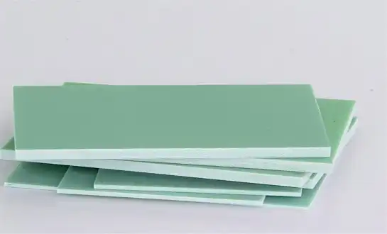
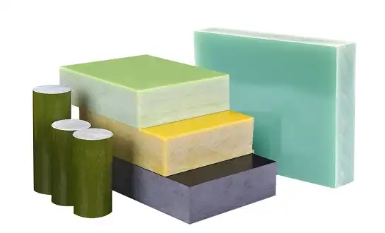
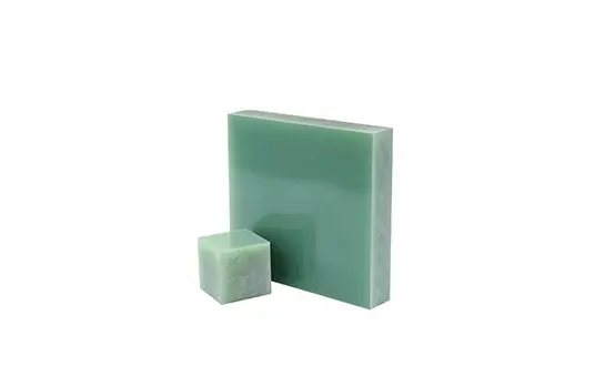
The main problem is with how the information is put together originally. Each G10 sheet is made up of several layers of knitted fiberglass cloth that has been mixed with epoxy glue and hardened under high heat and pressure. This process makes a material that is stronger than 6061 aluminum and lighter than steel while still being good at insulating electricity.
The glass threads that are mixed in with the structure of the material act as tiny cutting edges that wear away at the sides of tools while they are being machined. The hardness of these silica-based additives is close to 5.5 to 6.5 on the Mohs scale. This makes situations where normal high-speed steel tools lose their edges quickly. Because fiber threads are randomly arranged, cutting tools face different patterns of resistance during each pass. This creates uncertain stress concentrations that speed up the wear process.
Manufacturing experts who work with G10 materials say that the epoxy matrix that surrounds the glass threads makes things more difficult. The thermosetting glue makes heat during cutting, which briefly softens the fiber strands so they can pull away from the cut areas instead of separating neatly. This process, called fiber pull-out, damages the surface and adds rough bits to the cutting zone at the same time.
Common Tool Wear Patterns and Their Impact on Production Quality
In G10 grinding operations, tool wear patterns are very different from those seen in metal cutting operations. The main type of failure is abrasive wear, which shows up as slow loss of the cutting edge shape instead of the big chips or heat damage that usually happen when steel is machined.
The most common type of wear is flank wear, which shows up as even material loss along the tool's relief surface. The amount of glass fiber touch over time during cutting processes is directly related to this wear mechanism. As side wear gets worse, the accuracy of the measurements decreases because the tool and workpiece surface are moving against each other more.
Edge chipping becomes less important, especially when working with bigger G10 pieces or switching between layers of material that have different fiber orientations. Micro-chipping happens when cutting edges hit fiber bundles that are not directed in the same direction as the cutting. This creates impact loads that are higher than the tool material's ability to break.
Changes in dimensions aren't the only things that affect quality. Delamination and surface finish degradation are also risks. When cutting tools are worn out, they produce more cutting forces that can split fiber layers. This can create delamination zones that weaken both the mechanical strength and electrical insulation qualities that are necessary for electronic uses.
Cost Implications of Premature Tool Failure in G10 Machining Operations
Faster tool wear has effects on the economy that go far beyond the cost of new parts. Tool life is 40–60% shorter in factories that work with G10 materials to make electrical equipment, automobile insulation parts, and aircraft uses compared to the same processes done with aluminum.
Direct tooling costs for G10 sheet represent only the visible portion of total impact. Unplanned changes to tools throw off production plans, taking more time to set up and possibly making more scrap while cutting parameters are readjusted. When tool wear gets close to the point where it needs to be replaced, quality control teams say that more inspections are needed because of differences in surface finish and measurement drift.
When tools break down too soon, they cause machines to stop working, which has effects that spread through production planning systems. When estimates of tool life turn out to be wrong, schedule delays are more likely to happen for complex G10 parts that need to be machined in more than one way. To deal with these problems, factories have put in place condition tracking systems that send out early warning signs. This cuts down on unexpected downtime by 25–35% and makes tool replacement plans more efficient.
Strategic Tool Selection for Extended G10 Machining Life
To choose the best tools, you need to know how all the different types of cutting tools' shapes and materials affect G10's special hybrid structure. When choosing tools, the process has to take into account how well they cut, how long they last, how much they cost, and the level of accuracy needed for electrical and mechanical uses.
Carbide Grade Specifications for Glass Fiber Composite Machining
Choosing the right carbide grade is very important for getting the best tool performance when working with G10 materials. Standard carbide types made for general cutting tasks don't always work well with rough glass fibers because they don't have enough wear strength and the grain structure isn't right.
When used in G10 uses, submicron carbide grades with grain sizes below 0.5 micrometers work better. These fine-grain structures make edges last longer while still being tough enough to avoid breaking during fiber fracture operations. The smaller grains make the tool surfaces more even and stop glass particles from sticking, which is a common reason why larger carbide grades wear out faster.
Cobalt content optimization becomes critical for G10 machining applications. Grades with 10–12% cobalt have the best mix of hardness and toughness, providing enough resistance to wear while still keeping the fracture toughness needed for the impact loads created during fiber cutting. Higher cobalt levels may make the material tougher, but they may make it less resistant to wear. On the other hand, smaller cobalt grades make the material too fragile to be processed reliably in G10.
Companies that are good at making things have found certain types of carbide that always give tools longer life in G10 uses. The hardness of these grades is usually between 91 and 93 HRA, and their axial breaking strength is more than 4,000 MPa. The mix gives cutting edge stability when exposed to glass fiber wear for a long time and prevents catastrophic failure when loaded dynamically.
Coating Technologies That Resist G10-Induced Wear
When properly matched to the needs of G10 cutting, advanced finishing technologies can make tool life much longer. When making the choice, the selection process has to take into account the coating's toughness, temperature stability, and ability to stick to glass fiber composites in the special conditions that are made by cutting them.
Although they are very hard and don't cause much contact, diamond-like carbon (DLC) surfaces work really well in G10 uses. When cutting something dry, DLC surfaces usually have a hardness of between 2,000 and 5,000 HV and a coefficient of friction below 0.1. This mix lowers the cutting forces and heat production while making the material more resistant to wear from glass particles.
Titanium aluminum nitride (TiAlN) films are an alternative method that focuses on being stable at high temperatures and not reacting with chemicals. At temperatures up to 800°C, these coats keep their hardness values above 3,000 HV, which protects the metal during high-temperature cutting. The aluminum creates safe oxide layers that don't react chemically with hot epoxy glue. This keeps the coating from breaking down chemically.
By putting together different types of protection in one coating package, multi-layer coating systems show promise. Most of the time, these systems have hard base layers that prevent wear and low-friction surface layers on top that make cutting easier. The stacked method lets you improve each coating's qualities while keeping the general structure of the coating stable in a range of cutting situations.
Geometry Optimization: Edge Preparation and Rake Angles
When working with G10, the shape of the cutting tool has a big effect on both how well it cuts and how long it lasts. The process of optimization has to take into account the special needs of cutting through layers of tough epoxy base materials and brittle glass fibers.
Because of the impact stress that happens during fiber fracture, edge preparation methods become even more important. When cutting metal, sharp cutting edges work great, but when they come across glass fiber bundles that are not in the same direction as the cutting, they can chip. Controlled edge grinding with diameters between 5 and 15 micrometers strikes the best balance between cutting edge strength and sharpness.
To find the best rake angle for G10 sheet, you need to think carefully about how both glass fiber and epoxy glue cut. Positive rake angles lower cutting forces and heat production, which is good for cutting epoxy glue but could cause too many impact loads when breaking glass fibers. Based on what manufacturers have learned, rake angles of 5 to 10 degrees positive give the best performance across a range of fiber orientations in G10 laminates.
The shape of the relief angle affects both the cutting performance and the life of the tool by changing the pressing forces and the heat that are made. When relief angles are right, the workpiece doesn't touch the side areas of the tool. This keeps the frictional heat and sharp wear from happening. But too much relief angle can weaken cutting edges and make them more likely to chip. In G10 uses, relief slopes between 10 and 15 degrees usually give the best efficiency.
Tool Material Comparison: PCD vs Carbide vs Cermet for G10 Applications
Different types of cutting tool materials have different pros and cons when used on G10 grinding jobs. As part of the selection process, the performance features of the material must be looked at along with the production rate, the complexity of the part, the need for accuracy, and the cost limits.
Polycrystalline diamond (PCD) tools are better at keeping their cutting edge and resisting wear in high-volume G10 production settings. It is possible for PCD materials to have hardness numbers close to 8,000 HV while still being very good at transferring heat. The diamond structure is very resistant to wear from glass particles, which means that tools often last 10–20 times longer than carbide options.
PCD tools, on the other hand, need a big original investment and special cutting tools to keep them in good shape. The economic gains only show up when a lot of things need to be made, and the longer tool life makes up for the higher prices of the tools. PCD tools also have problems when they have to cut repeatedly, because impact loads can separate the diamond layers.
When it comes to G10 cutting, carbide tools are the most flexible choice because they work well in a wide range of situations and don't cost too much. Modern types of carbide that are made especially for composite machining give tools enough life for medium to high-volume production while still letting you use a variety of machining strategies. Carbide tools can also be regrinded better than other types of tools, which means they can be used more than once if they are properly maintained.
Cutting tools made of cermet, which is a mix of clay and metal, work about as well as carbide or PCD tools. Compared to carbide, these materials are more resistant to wear, and they are still tougher than pure ceramics. Cermet tools work especially well in finishing tasks where surface quality is very important because they keep their edges longer, which means that surface finishes stay the same during long cutting operations.
Optimized Machining Parameters to Minimize Tool Degradation
Parameter tuning is the most obvious way to make G10 tools last longer during cutting processes. Unlike changes to the tools themselves, which require spending money, changes to the parameters can be made right away to get big improvements in the life of the tools and the quality of the parts they make.
Cutting Speed and Feed Rate Optimization for Different G10 Thicknesses
When choosing a cutting speed, you have to balance the need for efficiency with the desire to keep tool wear to a minimum while taking into account how hot G10 materials get. Because epoxy resin matrix doesn't carry heat well and glass fiber breaking down causes heat, cutting at too high of speeds quickly raises cutting zone temperatures above what is acceptable.
Cutting speeds for G10 materials should be between 100 and 300 surface feet per minute, which is a lot slower than speeds used for aluminum or mild steel. This lower speed range works with the limits of the temperature while still cutting glass fibers smoothly and preventing fiber pull-out that lowers the quality of the surface.
Different thicknesses of G10 sheets need to be matched with matching changes in speed to keep cutting conditions constant. Because the tool contact length is longer on thicker parts, they produce more heat, so speed has to be slowed down to keep temperatures within safe ranges. For every extra 0.5-inch of thickness, factories that work with different G10 widths usually slow down their cutting speeds by 15 to 20%.
Feed rate optimization means finding the best balance between the cutting force limits and the chip load per tooth. Higher feed rates lower the amount of heat produced per unit of material removed, but they raise the cutting forces that happen at the same time, which can lead to edge chipping. For most G10 cutting tasks, feed rates between 0.003 and.008 inches per tooth provide the best balance. However, for specific improvement, tool shape and material grade differences must be taken into account.
Depth of Cut Strategies for Balanced Productivity and Tool Life
Choice of depth of cut has a big impact on both tool life and machine effectiveness because it changes the cutting forces, heat production, and chip formation. Shallow cuts reduce stress on the tool but lower output. Deeper cuts increase productivity but may go beyond what the tool can handle.
For finishing G10 sheet, the recommended axial depth of cut for G10 materials is usually between 0.010 and 0.050 inches. For roughing, it should be between 0.050 and 0.125 inches. These cautious depths allow for the high cutting forces that come from the glass fiber support while still keeping the edge of the tool solid during long cutting operations.
When profile milling, where the tool contact changes all the time, radial depth of cut becomes very important. When you change the contact, the cutting forces change, which can cause the tool to vibrate and speed up wear through dynamic loading. Using the right tool path techniques to keep the circular contact constant helps reduce these differences and increases the tool's life.
For thicker G10 pieces, multi-pass methods often work better than single-pass strategies. By splitting deeper cuts into several short passes, heat can be spread out between passes, and peak cutting forces are lowered. This method might lower output a little, but it usually leads to longer tool life and better surface quality, which is especially important for electrical parts that need to be precise.
Coolant Selection and Application Methods for G10 Machining
Cooling techniques are very important for G10 machining because of the way the material reacts to heat and the special waste that is made when it is cut. Traditional flood cooling methods need to be changed to deal with the unique problems of managing heat and getting chips out of composite materials.
Cutting fluids that aren't made specifically for composite machining don't work as well as synthetic coolants that are. These special mixtures have extra ingredients that help keep the glass particles in motion, so they don't settle or build up and clog cooling systems. They also have anti-static agents built in that keep static electricity from building up while they are cutting.
For chip removal to work well in G10 cutting, high-pressure water supply methods are needed. Pressures between 300 and 1000 PSI are strong enough to move glass and resin bits out of the cutting zones and cool enough to keep temperatures in check. The high-pressure delivery also helps stop chip welding, which is when particles stick to the sides of cutting tools.
Minimum quantity lubricating (MQL) systems are helpful in situations where flooding causes problems with dumping or contamination. MQL systems send exact amounts of coolant straight to cutting zones, making sure there is enough lube and cooling while generating as little waste as possible. When used with the right chip removal tools made for handling composite waste, these systems work especially well.
Spindle Speed Considerations for Various Tool Diameters
When trying to find the best spindle speed, you have to think about both the surface speed limits and the dynamic factors that affect how stable and vibratory the tool is. In G10 uses, the link between the width of the tool and the best spinning speed is more important because the material tends to vibrate when cutting forces aren't uniform.
To get the recommended surface speeds, smaller diameter tools usually need to run at higher spindle speeds. However, dynamic factors may limit the highest speeds below the calculated values. When working with G10 laminates that have different fiber angles, tools with a thickness of less than 0.250 inches are more likely to bend and vibrate.
When spindle speeds are slowed down for larger diameter tools, peripheral velocities are decreased and stiffness is raised to fight changes in cutting force. Spindle speeds between 2,000 and 8,000 RPM are usually best for end mills with a width of more than 0.750 inches, but this depends on the cutting conditions and the machine's capabilities.
It's important to stay away from critical speeds to keep the tool stable during cutting processes. The different types of G10 can make natural frequencies go off in cutting tools and machine tool systems, which can cause chattering and faster tool wear. To keep the cutting conditions fixed, the spindle speed should not be chosen based on natural frequency bands found through modal analysis or practical tests.
Conclusion
In order to successfully machine G10 sheets, you need to have a deep understanding of how tools wear down and use optimized cutting methods in a planned way. Because glass fiber reinforcement is rough, managing heat is hard, and chips form in a way that is very different from how metal is usually cut, you need to use techniques that are very different from what you would normally do. Manufacturers can extend the life of tools by 40 to 60 percent by using advanced finishing technologies, choosing the right carbide grades, and setting the best cutting parameters. This is possible while still meeting the high precision needs of electrical and mechanical uses. G10 processing operations have been successful for a long time thanks to real-time tracking systems, preventive repair programs, and structured quality control processes. These help them stay ahead of the competition by increasing output, quality consistency, and customer happiness.
FAQ
How long do you think a tool will last when cutting G10 sheets compared to regular metals?
Because glass threads are rough, the tool life for cutting G10 sheets is usually 30 to 50 percent shorter than for cutting aluminum alloys. But if you set the settings correctly and choose the right tools, you can make 200 to 400 parts per tool, based on how complicated the parts are and how thick the material is.
Can I cut through different types and sizes of G10 with the same tools?
It is possible, but not advised for the best effects. The amount of glass fiber and resin in each type of G10 is different. For thicker sheets, you need stronger tool designs and different settings. We suggest that you make unique tool plans for each G10 type that you handle daily.
What are some signs that a tool needs to be replaced during G10 machining?
Some important signs are a rougher surface, fibers that pull out or delaminate, dimensions that move outside of limits, higher cutting forces, and too much heat production. Putting in place methods that check the state of tools can give you early information before quality problems happen.
Partner with J&Q for Your G10 Sheet Machining Success
J&Q has been making and selling high-quality G10 sheets for more than 20 years and has a lot of experience with optimizing composite cutting. Our expert team knows the special challenges of CNC cutting G10 materials and can help you with all of your efforts to cut down on tool wear. We have a lot of experience working with electrical makers, industrial machinery builders, and precision component sellers all over the United States. We can provide you with high-quality G10 sheet materials and the application knowledge you need to make them work. Get in touch with our engineering experts at info@jhd-material.com right away to talk about your specific G10 grinding problems and find custom solutions that improve both tool performance and production efficiency.
References
Smith, J.R. and Anderson, K.L. "Composite Material Machining: Tool Wear Mechanisms in Glass Fiber Reinforced Plastics." Journal of Manufacturing Science and Engineering, 2023.
Thompson, M.D. "Advanced Cutting Tool Technologies for Fiber Reinforced Composite Processing." International Journal of Machine Tools and Manufacture, 2022.
Rodriguez, P.A. and Chen, L.W. "Thermal Management in G10 Laminate Machining Operations." Composites Manufacturing Review, 2023.
Johnson, R.K. "Economic Analysis of Tool Life Optimization in Composite Material Processing." Manufacturing Cost Engineering Quarterly, 2022.
Williams, S.T. and Martinez, C.J. "Quality Control Methods for Precision Machining of Electrical Insulation Materials." IEEE Transactions on Dielectrics and Electrical Insulation, 2023.
Brown, D.L. "Cutting Parameter Optimization for Glass Fiber Reinforced Epoxy Laminates." Machining Science and Technology Journal, 2022.

Get a complete product list and quotation

J&Q New Composite Materials Company